Wave User Manual 45
Version 4
NOTE: The pulse width is automatically set when setting the probe
frequency. Although this parameter is calculated automatically, it
corresponds to 0.5/frequency in square mode. In spike mode, it is
equal to 50 ns.
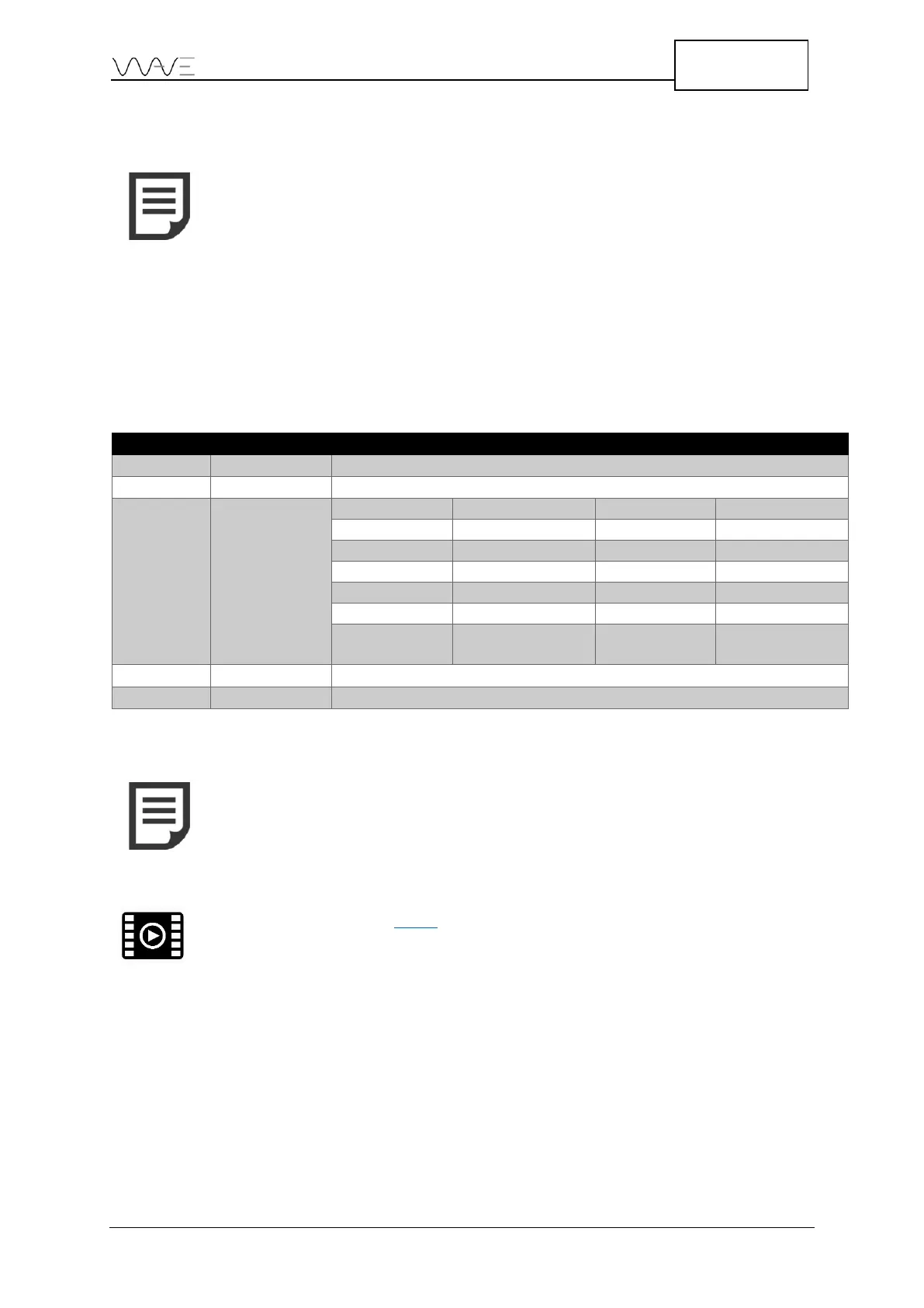
8.3 Signal Menu
The A-Scan view can be modified in different ways. The signal itself can be changed by
applying different filters or by choosing a rejection mode and rejection level.
Table 15 - A-Scan signal appearance
None, Suppressive, Linear
NOTE: Some parameters can only take two (2) different values. When
changing the value of such binary type parameters, hitting the on-
screen button will immediately toggle the parameter value. The Ruler
Mode parameter is one of these parameters as it can only take one
of two values: Distance or Time.
View the following video for more details about the A-Scan
rectification.