Wave User Manual 35
Version 4
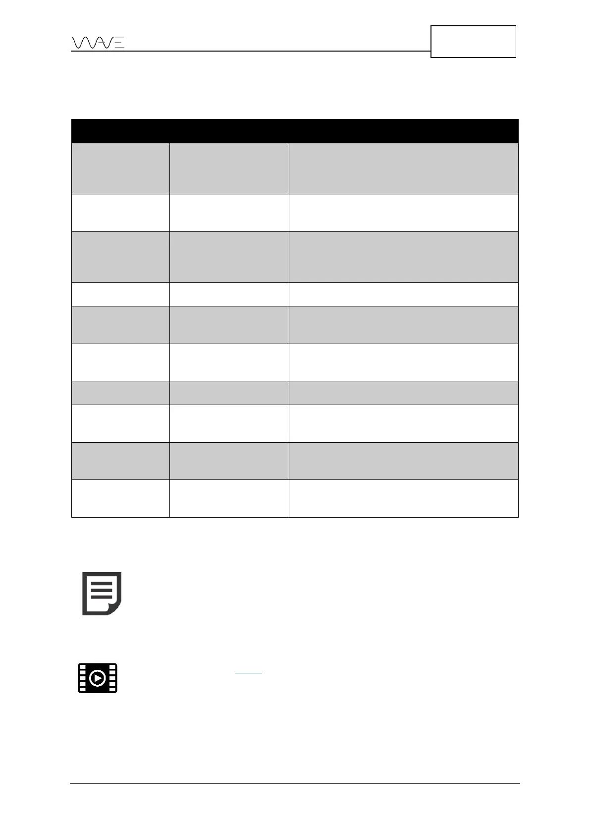
The following table shows the various measurement choices for different gates.
Table 10 - Measurement choices versus gates
%FSH, Sound Path, Depth, True Depth, Surface
Distance, Surface Distance Minus X Offset,
%Ref, dB Ref
Sound Path, Depth, True Depth, Surface
Distance, Surface Distance Minus X Offset
%FSH, Sound Path, Depth, True Depth, Surface
Distance, Surface Distance Minus X Offset, %Ref,
dB Ref
%FSH (that is the gate level)
Sound Path, Depth, True Depth, Surface
Distance
Sound Path, Depth, True Depth, Surface
Distance
Sound Path, Depth, True Depth, Surface
Distance
Sound Path, Depth, True Depth, Surface
Distance, Surface Distance Minus X Offset
Sound Path, Depth, True Depth, Surface
Distance, Surface Distance
NOTE: The Gate Start and Gate Stop positions in the table above can
be expressed in a number of different ways. The usual way of
representing theses positions is based on the sound path. It might
also be useful to express them relative to the depth, the true depth
or the surface distance. This allows you to better understand which
part of the piece being expected is covered by the gate.
View the following video for how to change the measurements.