Shanghai STEP Electric Corporation
Chapter 8 Elevator Elevator Commissioning Guide
Integrated drive controller uses original non-load sensor start-compensation technology, so
even if there is no pre-load device for start compensation, it can also be adjusted by parameters to
achieve good starting comfort.
(a) Conventional method for adjusting starting comfort
Under normal circumstances, adjust the inverter's zero servo PID parameters and the
excitation time and other parameters, to improve the starting comfort. Refer to the Table below for
relevant adjustment parameters.
Gain value of PID regulator
that takes effect on zero servo
Integral value of PID regulator
that takes effect on zero servo
Zero servo
differential D0
Differential value of PID
regulator that takes effect on zero
servo
Start accelerated movement
after the inverter gives operating
signal and this time maintains
torque.
Note 1:
The speed at the starting point to be adjusted around PID regulator
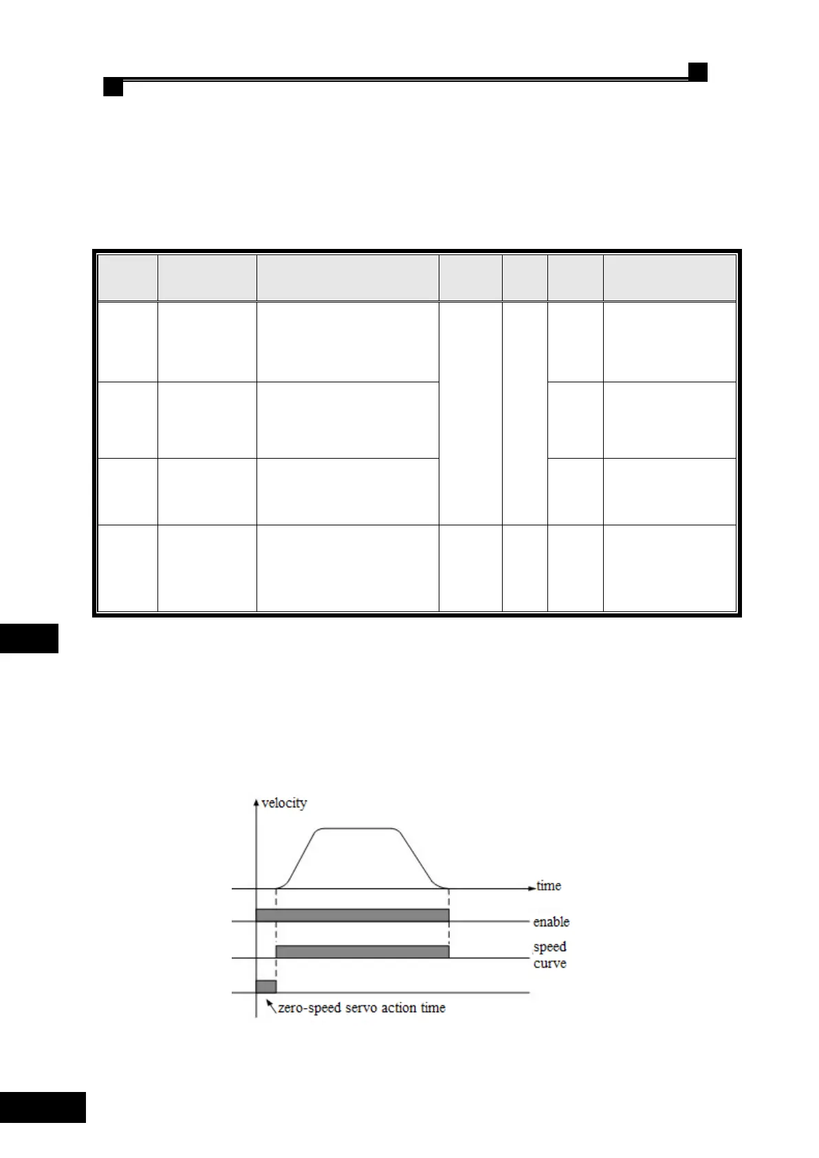
F226 is a zero servo time parameter, used to adjust and control the delay time given by the system
speed curve; this time is also the action time of PID regulator P0, I0, and D0 at zero servo (or zero
speed). See the following for the detailed timing sequence diagram.
Fig 8.1 Zero Servo Timing Sequence Diagram
 Loading...