EasyManuals Logo

STEP AS380 Series User Manual

Default Icon
300 pages
To Next Page IconTo Next Page
To Previous Page IconTo Previous Page
Page #60 background imageLoading...
Page #60 background image
Shanghai STEP Electric Corporation
50
Chapter 4 The Wiring Of Elevator integrated Drive Controller
Name
Pin No
Label
Function
Specification
input
JP2.2
A-
Phase A signal -
JP2.3
B+
Phase B signal +
JP2.4
B-
Phase B signal -
JP2.5
Z+
Phase Z signal +
JP2.6
Z-
Phase Z signal -
JP2.7
V
Anode of encoder power
Voltage: 12VDC, Max output current: 500mA
JP2.8
V-
Cathode of encoder power
JP2.9
PE
Shielded ground
Grounding terminal for shielded cable
4.7.1.4 Wire requirement for incremental ABZ 12V PG card input
terminal and encoder output
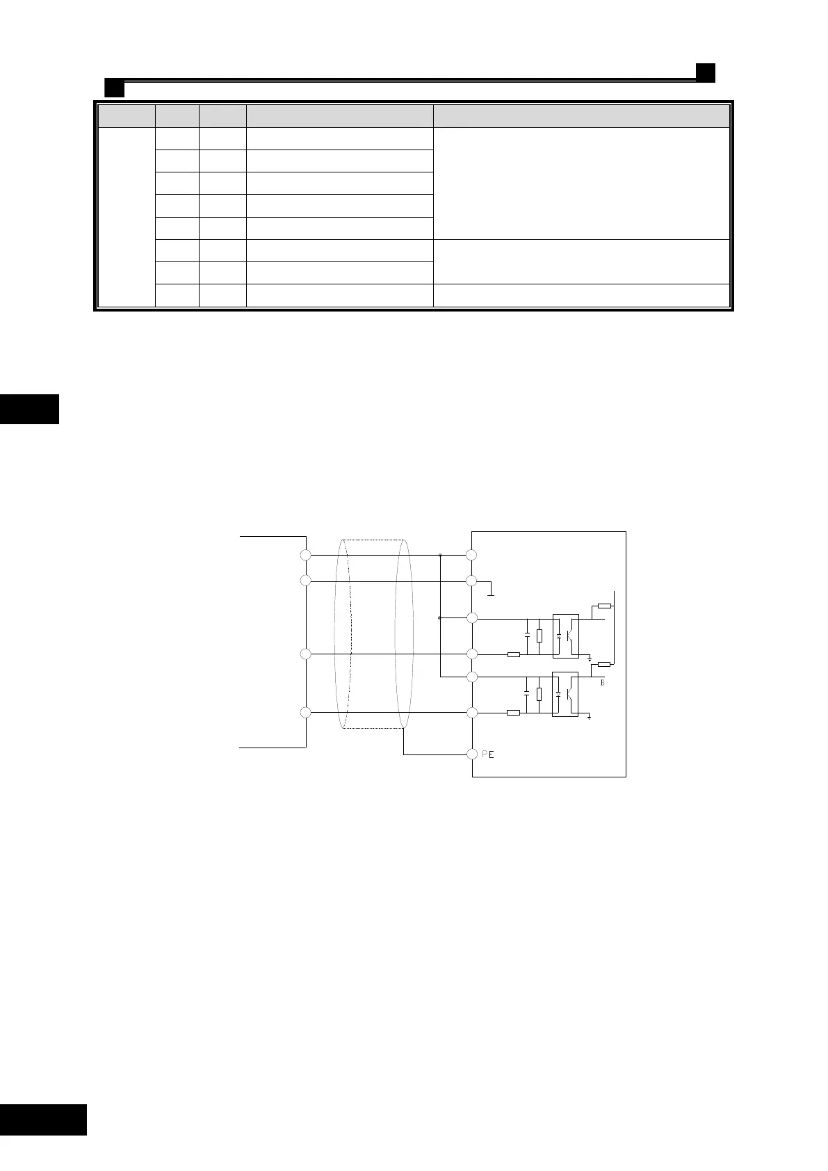
Incremental ABZ 12V PG card (AS.T025) can receive two kinds encoder signals: open
collector signal and push-pull signal.
Encoder wiring by open collector signal, see Fig. 4.23.
Open collector output
VCC
0V
A
B
A-
B-
A+
B+
A
PG card terminal block
+5V
Shielded cable
grounding
V+
V-
Fig. 4.23 Wiring with encoder open collector signal
Encoder wiring by push-pull signal, see Fig. 4.24.

Table of Contents

Questions and Answers:

Question and Answer IconNeed help?

Do you have a question about the STEP AS380 Series and is the answer not in the manual?

STEP AS380 Series Specifications

General IconGeneral
BrandSTEP
ModelAS380 Series
CategoryController
LanguageEnglish

Related product manuals