Shanghai STEP Electric Corporation
Chapter 4 The Wiring Of Elevator integrated Drive Controller
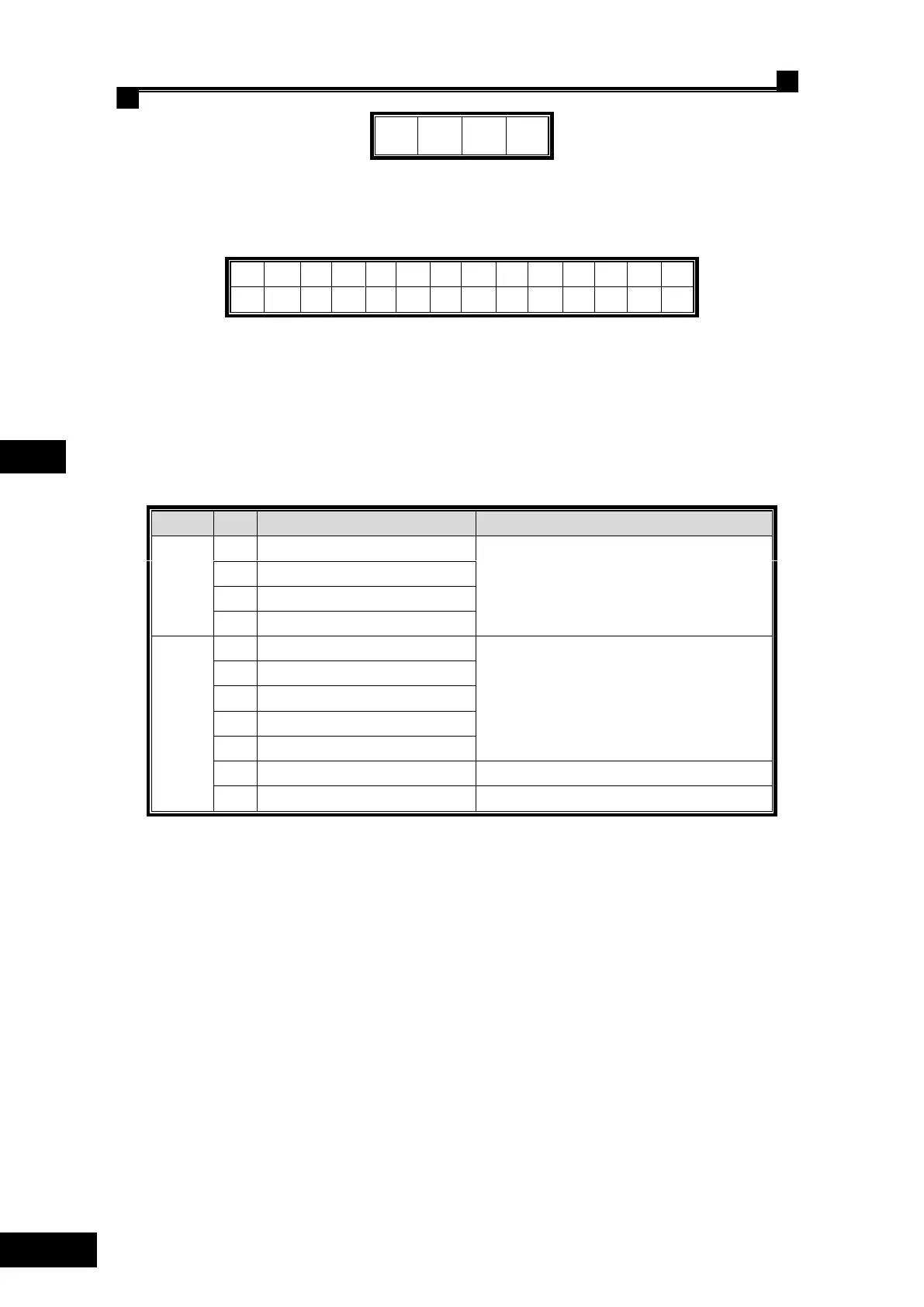
Fig. 4.26 The connection terminal JP3 lables of the SIN/COS PG card
JP2 terminal label: (14 pin socket):
Fig. 4.27 The connection terminal JP2 lables of the SIN/COS PG card
4.7.2.3 SIN/COS PG card terminal function specification
SIN/COS PG card (AS.T024) terminal function specification, see table 4.9.
Table 4.9 SIN/COS PG card terminal function specification
Divided frequency output, phase A
Triode open collector (max. frequency 100kHz)
Divided frequency output, phase B
Differential signal, max input frequency: 100kHz;
4.7.2.4 The wiring between SIN/COS PG card and encoder
SIN/COS PG can receive SIN/COS differential signal from encoder.
Wiring diagram for encoder, see Fig. 4.28.
 Loading...