Instruction Manual for AS380 Series Elevator Integrated Drive Controller
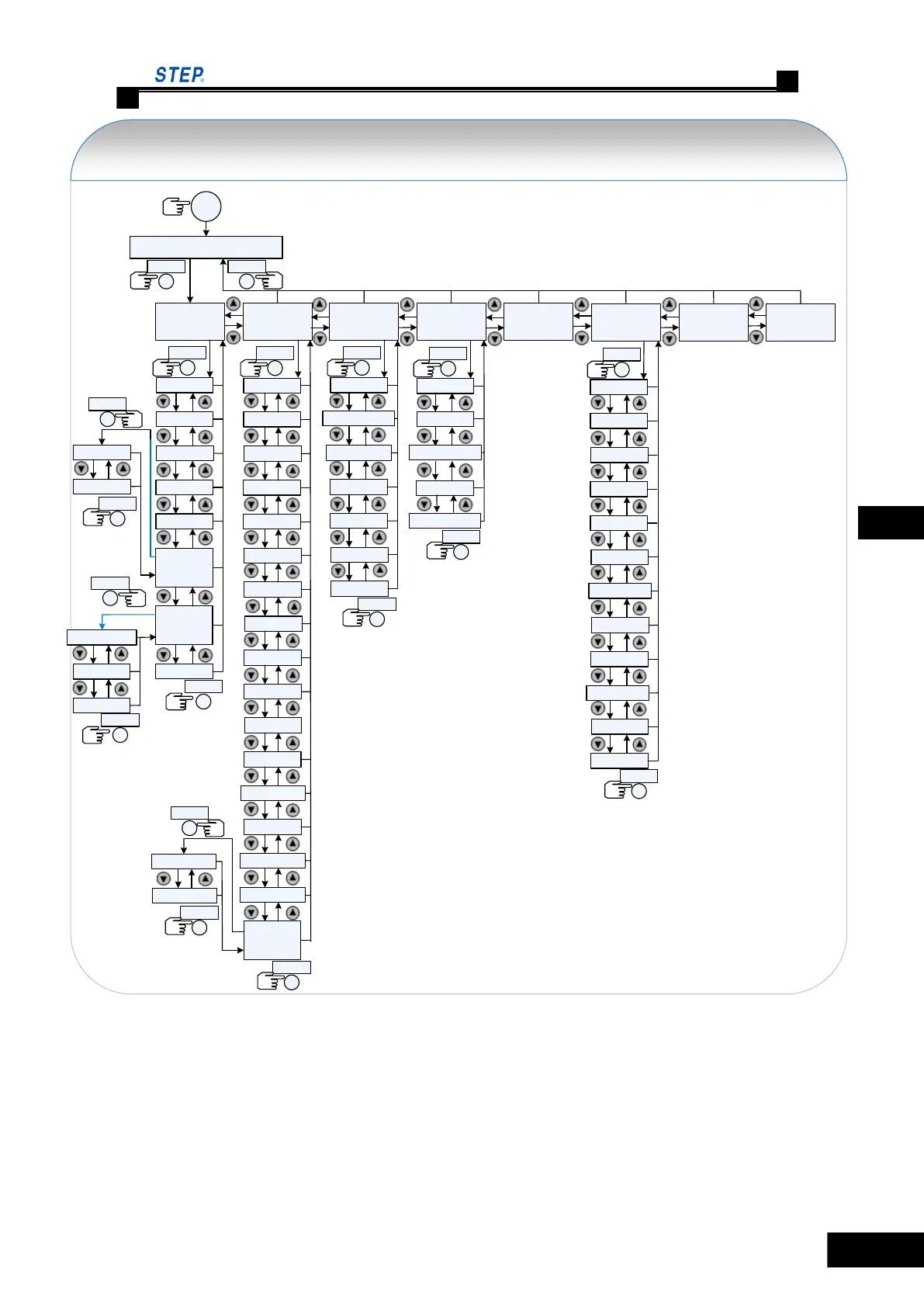
The menu structure of the handhold manipulator of AS380 integrated drive controller
Elevator status display
F1
Parameter
classification
ENTER ESC
Monitor status
Drive status
ENTER
Car call fucntion
Speed curve
Input /output
Fault record
Hoistway
data
Program version
Floor position
Switch p ositon
ENTER
ESC
Self-
diagnosis
Bus communication
evaluation
Encoder
evaluation
Hall call diagnosis
ENTER
ESC
ESC
Basic p arameter
ENTER
Comfort
adjustment
Elevator
specification
Motor
specification
Leveling
adjustment
Leveling fine-
tuning
Input types
Floor display
Door control
Open door
permissio n
Service landings
IC card setting
Service landing of
time slots
Parameter
summary
Control parameter
reset
Drive parameter
reset
Parameter
copy
Main board to
operator
Operator to main
board
ENTER
ESC
Debug Options
Hoistway self-
study
ENTER
Asynchronous motor
self-study
Leveling adju stment
mode
Terminal landing
call
Test running
Weighing debug
Door operation
ESC
ESC
Value-added
function
Time setting
ENTER
Floor bias
Set the base
landing
Fire-fighting
mode
Group control
mode
Return to base
landing mode
Arrival gong lead
Lighting time
Driver mode
Call classification
Double-click to
cancel call
Main board
validity period
ESC
Intelligent
debugging
Leveling adjust
ENTER
Parameter table
copy
Leveling fine-
tuning
NO/NC self-study
Port definition copy
ESC
Reset command
ReLogin
Change
password
Pic 5.6 Function status switch
Press Enter key after users select one function to enter the relevant detailed function window.
5.2.4.4 Method to check monitor status
Take fault check recording 1 as an example:
 Loading...