STOBER 10 | Connection
02/2019 | ID 442728.05
117
10.5.2 X2A: Brake A
The brake of axis A is connected to X2A. All device types of the SI6 drive controller can control
a 24V
DC
brake as standard.
Information
Note that brakes from other manufacturers may be connected only after consultation with
STOBER.
Controllable brakes
Note the technical data of the brakes controllable at X2A; see the chapter Controllable brakes
[}64].
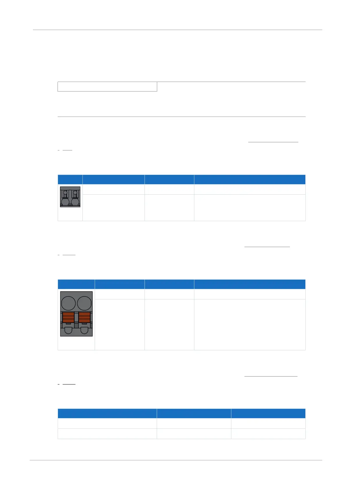
Sizes 0 to 2 (single-axis controllers)
Term. Pin Designation Function
5 | 6
5 1BD1 Brake actuation
6 1BD2 Reference potential
Tab. 96: X2A connection description, brake A, sizes 0 to 2 (single-axis controllers)
For connecting wiring, observe the terminal specifications in the chapter BCF 3,81 180 SN
[}233].
Sizes 2 (double-axis controllers) and 3
Term. Pin Designation Function
5 | 6
5 1BD1 Brake actuation
6 1BD2 Reference potential
Tab. 97: X2A connection description, brake A, sizes 2 (double-axis controllers) and 3
For connecting wiring, observe the terminal specifications in the chapter BFL 5.08HC 180 SN
[}233].
Cable requirements
Motor connection Size 0 to 2 Size 3
Without output choke 50m, shielded 100m, shielded
With output choke 100m, shielded —
Tab. 98: Maximum cable length of the power cable [m]