STOBER 10 | Connection
02/2019 | ID 442728.05
127
10.5.11 X20A: Motor A
The motor of axis A is connected to X20A.
UL-compliant operation
The external motors which are connected to the inverter units SI6 units shall not be grounded
over the modular drive system. The bonding/grounding of the motor(s) shall occur in the end
use application in accordance with the requirements of applicable electrical codes/standards.
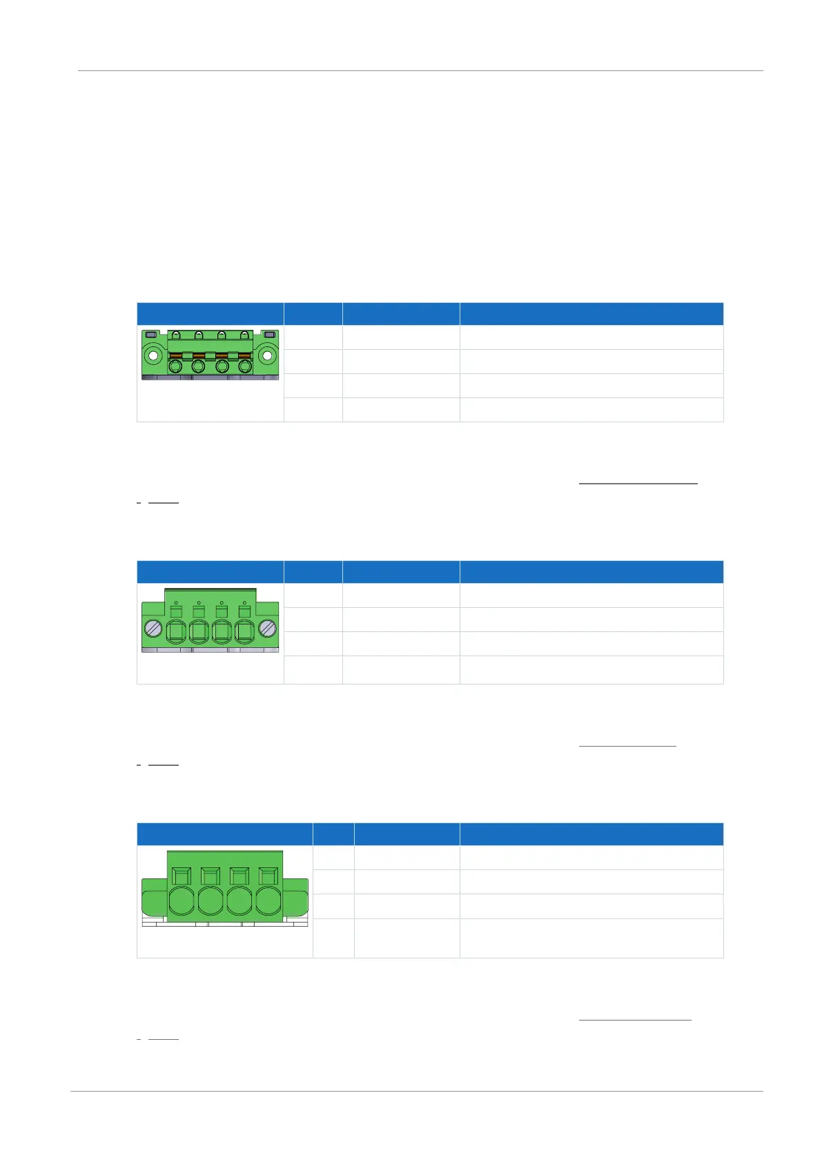
Size 0
Terminal Pin Designation Function
1 | 2 | 3 | 4
1 U Phase U motor connection
2 V Phase V motor connection
3 W Phase W motor connection
4 PE Grounding conductor
Tab. 117: X20A connection description, size 0
For connecting wiring, observe the terminal specifications in the chapter GFKC 2,5 -ST-7,62
[}235].
Sizes 1 and 2 (single-axis controllers)
Terminal Pin Designation Function
1 | 2 | 3 | 4
1 U Phase U motor connection
2 V Phase V motor connection
3 W Phase W motor connection
4 PE Grounding conductor
Tab. 118: X20A connection description, sizes 1 and 2 (single-axis controllers)
For connecting wiring, observe the terminal specifications in the chapter SPC 5 -ST-7,62
[}236].
Sizes 2 (double-axis controllers) and 3
Terminal Pin Designation Function
1 | 2 | 3 | 4
1 U Phase U motor connection
2 V Phase V motor connection
3 W Phase W motor connection
4 PE Grounding conductor
Tab. 119: X20A connection description, sizes 2 (double-axis controllers) and 3
For connecting wiring, observe the terminal specifications in the chapter SPC 16 -ST-10,16
[}237].