STOBER 6 | Technical data
02/2019 | ID 442728.05
43
6.3 Drive controllers
The following chapters contain specifications for the electrical data, dimensions and weight of
the drive controller.
6.3.1 Electrical data
The electrical data of the available SI6 sizes can be found in the following sections.
An explanation of the symbols used for formulas can be found in Chapter Symbols in formulas
[}246].
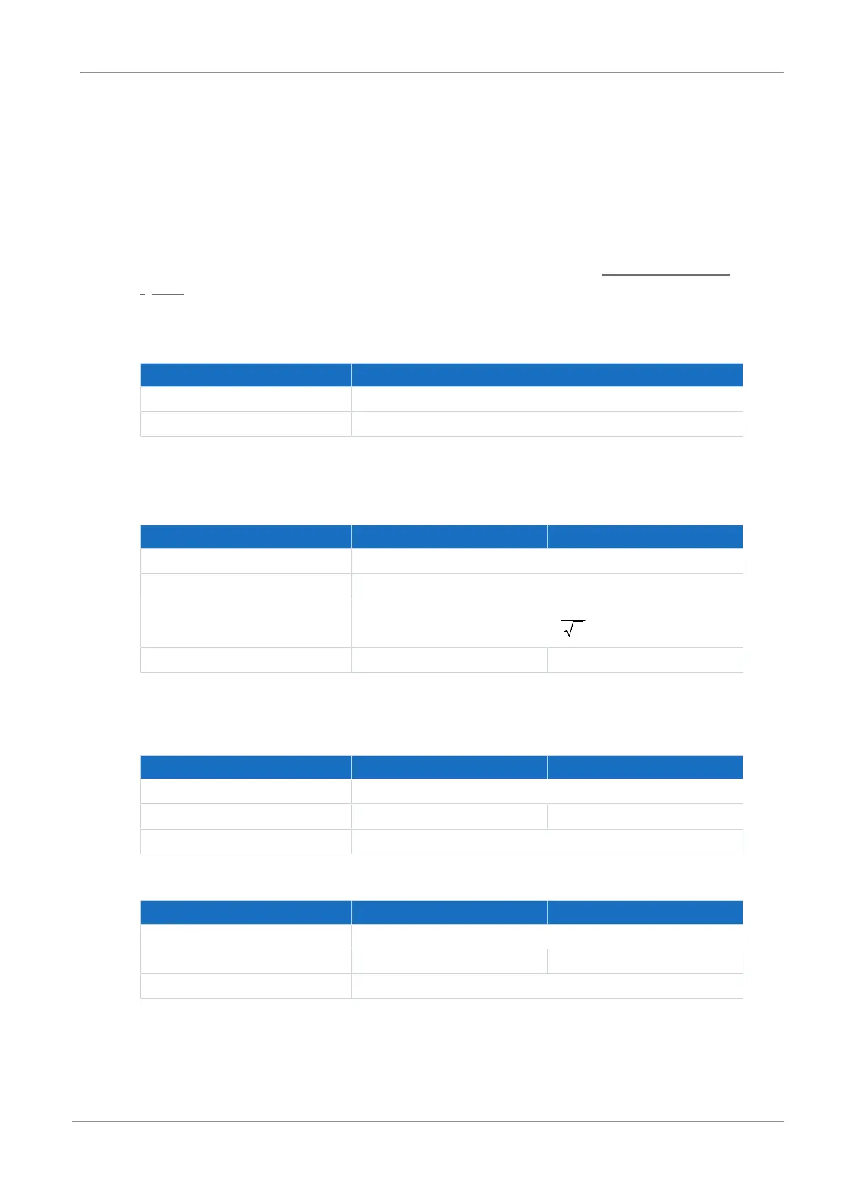
6.3.1.1 Control unit
Electrical data All types
U
1CU
24V
DC
, +20%/−15%
I
1maxCU
0.5A
Tab. 23: Control unit electrical data
6.3.1.2 Power unit: Size 0
Electrical data SI6A061 SI6A062
U
1PU
280–800V
DC
f
2PU
0–700Hz
U
2PU
0–max.
C
PU
180µF 270µF
Tab. 24: SI6 electrical data, size 0
Nominal currents up to +45°C (in the control cabinet)
Electrical data SI6A061 SI6A062
f
PWM,PU
4kHz
I
2N,PU
5A 2×5A
I
2maxPU
210% for 2s
Tab. 25: SI6 electrical data, size 0, at 4kHz clock frequency
Electrical data SI6A061 SI6A062
f
PWM,PU
8kHz
I
2N,PU
4.5A 2×4.5A
I
2maxPU
250% for 2s
Tab. 26: SI6 electrical data, size 0, at 8kHz clock frequency