STOBER 16 | Appendix
02/2019 | ID 442728.05
241
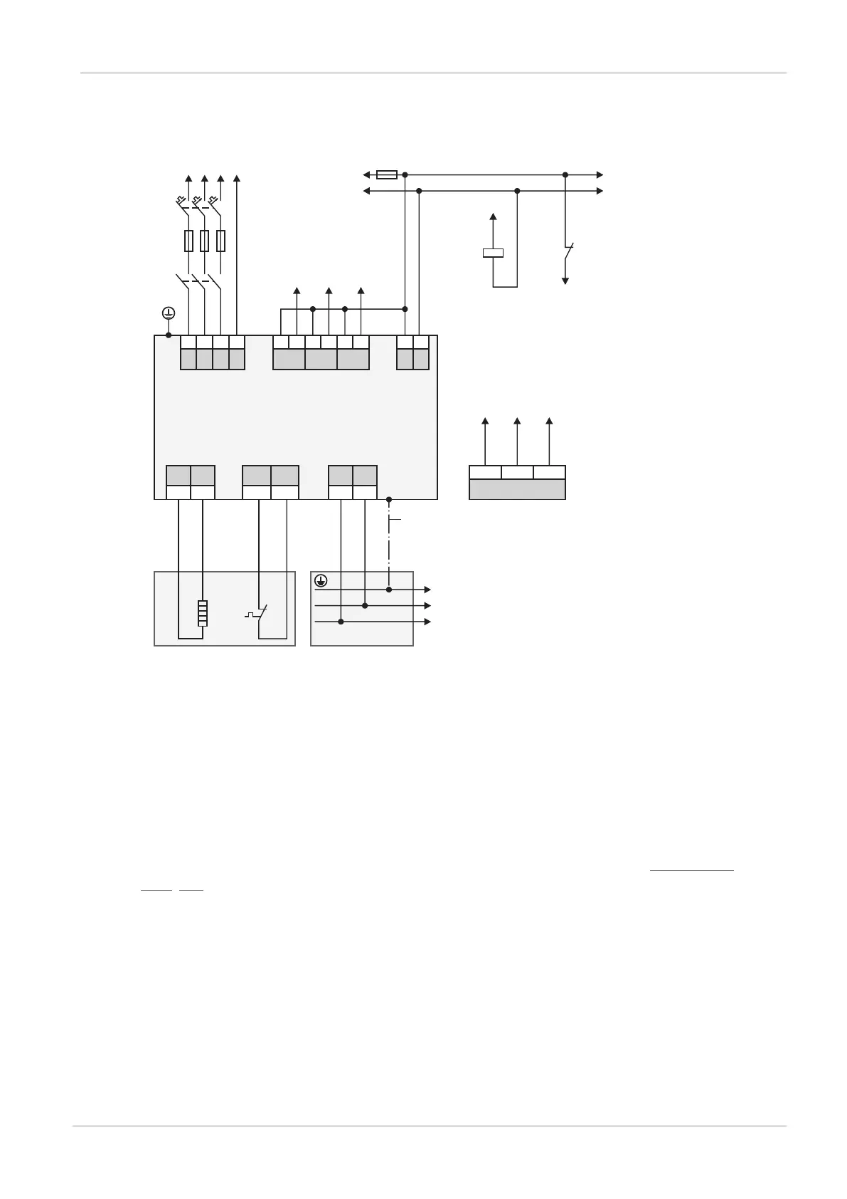
16.2.3 UL-compliant connection of the supply module
X21
X23
X22
PS6
X10
L1 L2
L3
PE
1 2
3
4
1 2 1 2 1 2
RB RB
1TP1 1TP2
D- D+
X11
+
-
1 2
F3
R1
X100
RDY
WAR1 WAR2
1 2
3
4
5
6
M
DC-
DC+
24 V
DC
1
T1
PEL1 L2
L3
F2
F1
DL6B
DI2
DI0
Q1.A1
1 2
3
A1
DI0
Q1.12
DI2
Q1
Q1.A1
Q1.12
A1
A2
11
12
Q1
Q1
Digital input
A1 Controller
F1 – F3 Fuse
L1 – L3 Three-phase power supply
T1 Supply module
R1 Braking resistor
Q1 Circuit breakers
1 Spring-loaded contact between DL6B and PS6
For UL-compliant operation:
For project configuration of the braking resistor, observe the notes in the chapter UL-compliant
use [}19].
The chassis of the PS6A/SI6A units is to be bonded through the M6 grounding studs on the
PS6A units (4.0Nm, 35Lb.inch).