STOBER 9 | Installation
02/2019 | ID 442728.05
95
9.6 Installing the DC link connection
Observe the installation notes when installing the DC link connection and associated hardware
components.
9.6.1 Order overview of the components for the DC link
connection
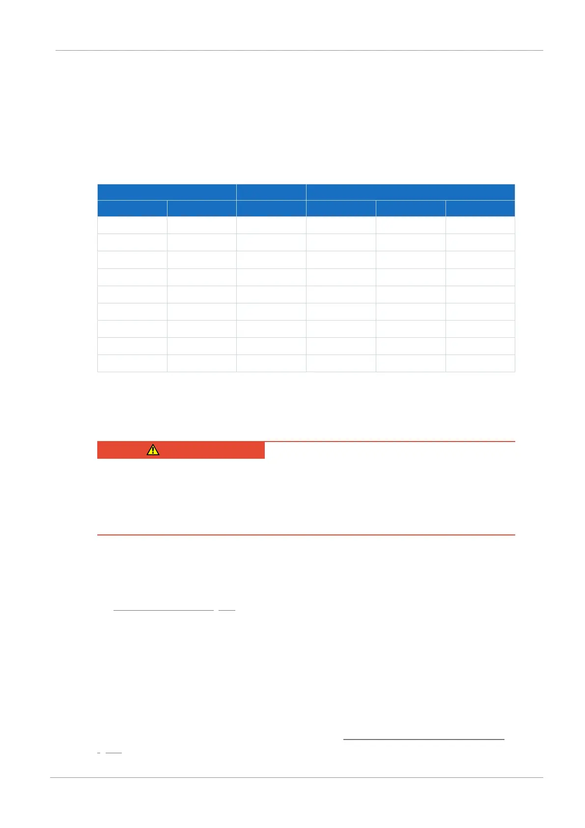
Device Terminal set Quick DC-Link
Type ID No. ID No. Type ID No. Width [mm]
PS6A24 56650 138660 DL6B20 56656 45
PS6A34 56651 138661 DL6B21 56658 65
SI6A061 56645 138655 DL6B10 56655 45
SI6A062 56646 138656 DL6B10 56655 45
SI6A161 56647 138657 DL6B11 56656 65
SI6A162 56648 138658 DL6B11 56656 65
SI6A261 56649 138659 DL6B11 56656 65
SI6A262 56653 138662 DL6B12 56663 105
SI6A361 56654 138663 DL6B12 56663 105
Tab. 81: Overview of hardware components necessary for the DC link connection with ID No.
9.6.2 Installing the DC link connection
DANGER!
Electrical voltage! Risk of fatal injury due to electric shock!
▪ Always switch off all power supply voltage before working on the devices!
▪ Note the discharge time of the DC link capacitors. You can only determine the absence of
voltage after this time period.
Tools and material
You will need:
§ 3 copper rails with sufficient length and a cross-section of 5 x 12mm, see the chapter
Length of copper rails [}94]
§ The nut and washer assemblies (M5), insulation connection pieces and quick fastening
clamps included with the DL6B Quick DC-Link modules
§ The insulation end sections for the left and right termination of the group that are available
separately
§ Fastening screws and tool for tightening the fastening screws
Requirements and installation
Observe the basic installation instructions in the chapter Drive controllers and supply modules
[}89].