16 | Appendix STOBER
240
02/2019 | ID 442728.05
For UL-compliant operation:
The external motors which are connected to the inverter units SI6 units shall not be grounded
over the modular drive system. The bonding/grounding of the motor(s) shall occur in the end
use application in accordance with the requirements of applicable electrical codes/standards.
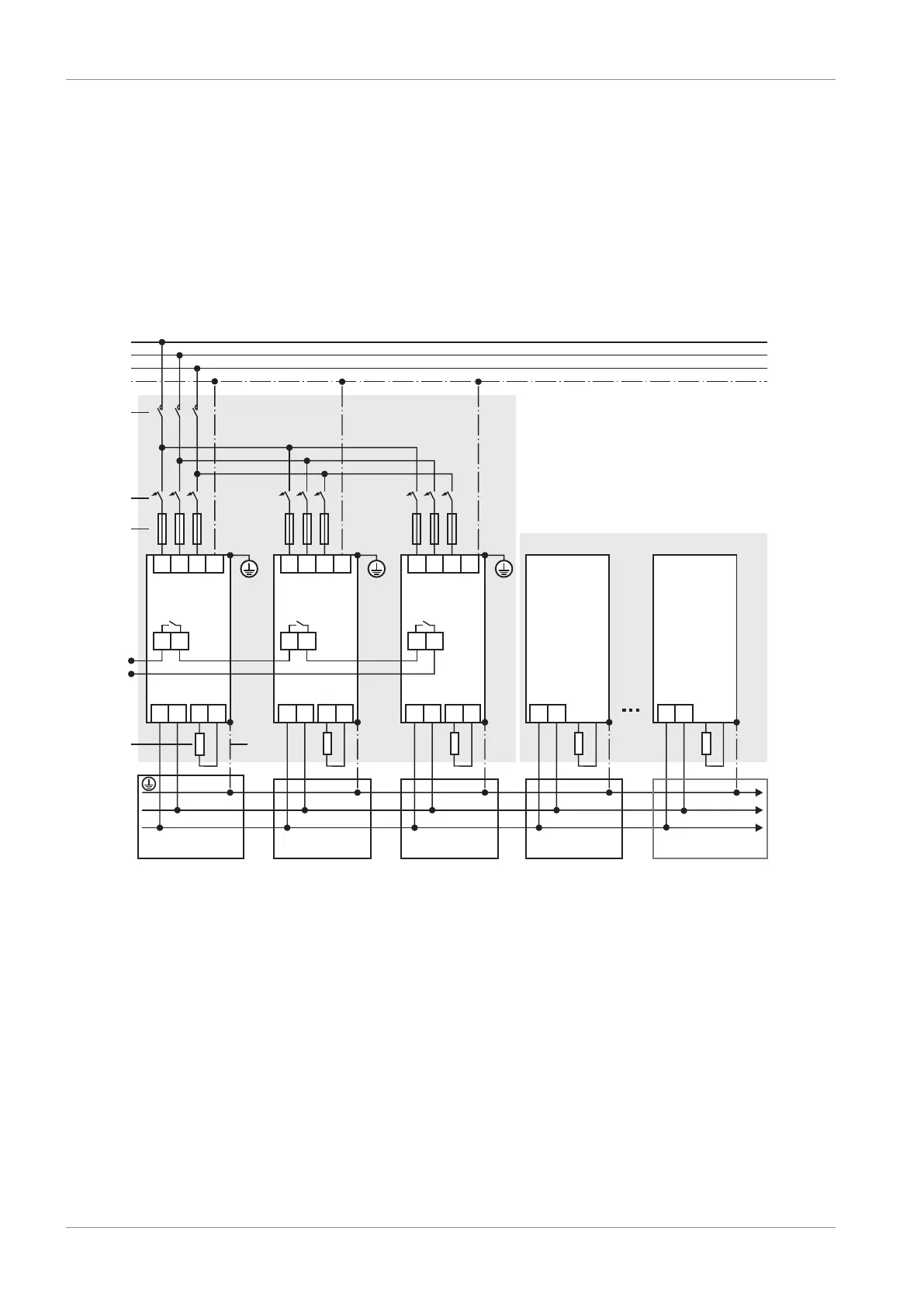
16.2.2 Parallel connection
The following graphic shows the principal connection of 3 PS6 supply modules and several SI6
drive controllers based on the DC link connection with DL6B Quick DC-Link.
PS6 SI6
X10
X100
1 2
L1
L2
L3
PE
PS6
SI6
1
2
3
4
X100
1 2
X100
1 2
X10 X10
PS6 PS6 SI6
L3
PE
L1 L2
L3
PE
L1 L2
L3
PE
L1 L2
DL6B
DL6B
DL6B
5
DL6B
D+
D-
6
D- D+ RB RB D- D+ RB RB D- D+ RB RB
X22 X21 X22 X21 X22 X21
D- D+
X22
D- D+
X22
DL6B
Fig.43: Wiring example with supply modules connected in parallel
1 Contactor
2 Overload protection
3 Short-circuit protection
4 Status relay
5 Braking resistor
6 Spring-loaded contact between DL6B and PS6 or SI6
For UL-compliant operation:
A single PS6A24 or PS6A34 supply module converts the AC (3-phase) input voltage into a
common DC bus output voltage, which is used to feed one or more SI6 drive controllers.