6 | Technical data STOBER
40
02/2019 | ID 442728.05
6.2.1.2 Power unit: Size 2
Electrical data PS6A24
U
1PU
3 × 400V
AC
, +32%/−50%, 50/60Hz;
3 × 480V
AC
, +10%/−58%, 50/60Hz
U
2PU
√2 × U
1PU
P
N,PU
10kW
I
1N,PU
25A
I
1maxPU
I
1N,PU
× 180% for 5s;
I
1N,PU
× 150% for 30s
C
maxPU
5000µF
Tab. 16: PS6 electrical data, size 2
6.2.1.3 Power unit: Size 3
Electrical data PS6A34
U
1PU
3 × 400V
AC
, +32%/−50%, 50/60Hz;
3 × 480V
AC
, +10%/−58%, 50/60Hz
U
2PU
√2 × U
1PU
P
N,PU
20kW
I
1N,PU
50A
I
1maxPU
I
1N,PU
× 180% for 5s;
I
1N,PU
× 150% for 30s
C
maxPU
10000µF
Tab. 17: PS6 electrical data, size 3
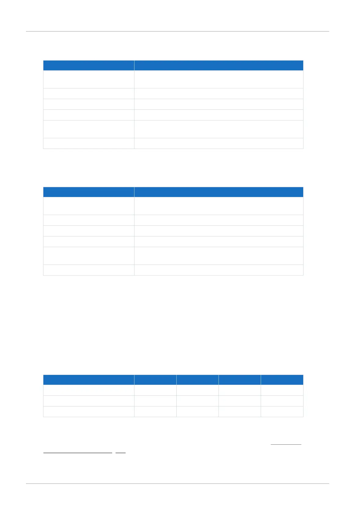
6.2.1.4 Parallel connection
The power and current increase if supply modules are connected in parallel. Take into account
that the total is derated by a factor of 0.8 in doing so.
The charging capacity of the supply modules can be increased by a parallel connection only if
the power grid supply is connected to all supply modules simultaneously. Increasing the
charging capacity also requires derating the total by a factor of 0.8.
The following table shows example combinations for parallel connection.
Electrical data 2 x PS6A24 3 x PS6A24 2 x PS6A34 3 x PS6A34
P
N,PU
16kW 24kW 32kW 48kW
I
1N,PU
40A 60A 80A 120A
C
maxPU
8000 µF 12000 µF 16000 µF 24000 µF
Tab. 18: Electrical data for parallel connection: Example combinations
Note the general conditions for parallel connection of supply modules in the chapter Information
on design and operation [}76].