10 | Connection STOBER
158
02/2019 | ID 442728.05
Length x [mm] Diameter y [mm]
78 26
Tab. 164: con.23 connector dimensions
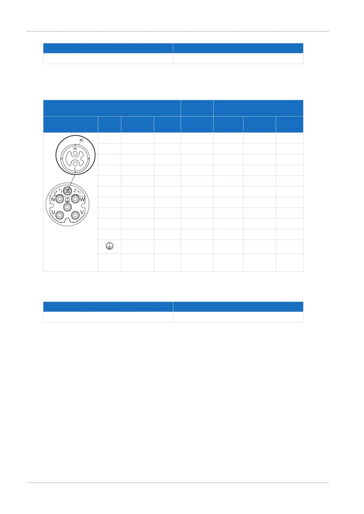
Hybrid cable – con.40 plug connector
Motor
(1)
Cable
(2)
Drive controller
(3) – (5)
Connection
diagram
Pin Designa-
tion
Core
color
Core No./
core color
Pin
X20
Pin
X2
Pin
X4
U 1U1 BK L1 1 — —
V 1V1 BU L2 2 — —
W 1W1 RD L3 3 — —
N — — — — — —
+ 1BD1 RD 1 — 5 —
− 1BD2 BK 2 — 6 —
F — — — — — —
G — — — — — —
H DSL+ GY WH — — 4
L DSL− GN BU — — 2
PE GNYE GNYE 4 — —
Hous-
ing
Shield — — Shield
contact
— —
Tab. 165: con.40 hybrid cable pin assignment
a) Coaxial shield to which the DSL shield is connected.
Length x [mm] Diameter y [mm]
99 46
Tab. 166: con.40 connector dimensions