STOBER 9 | Connection
05/2019 | ID 442790.01
109
9.6.2.3 Differential HTL incremental encoders
Suitable encoder cables are described below.
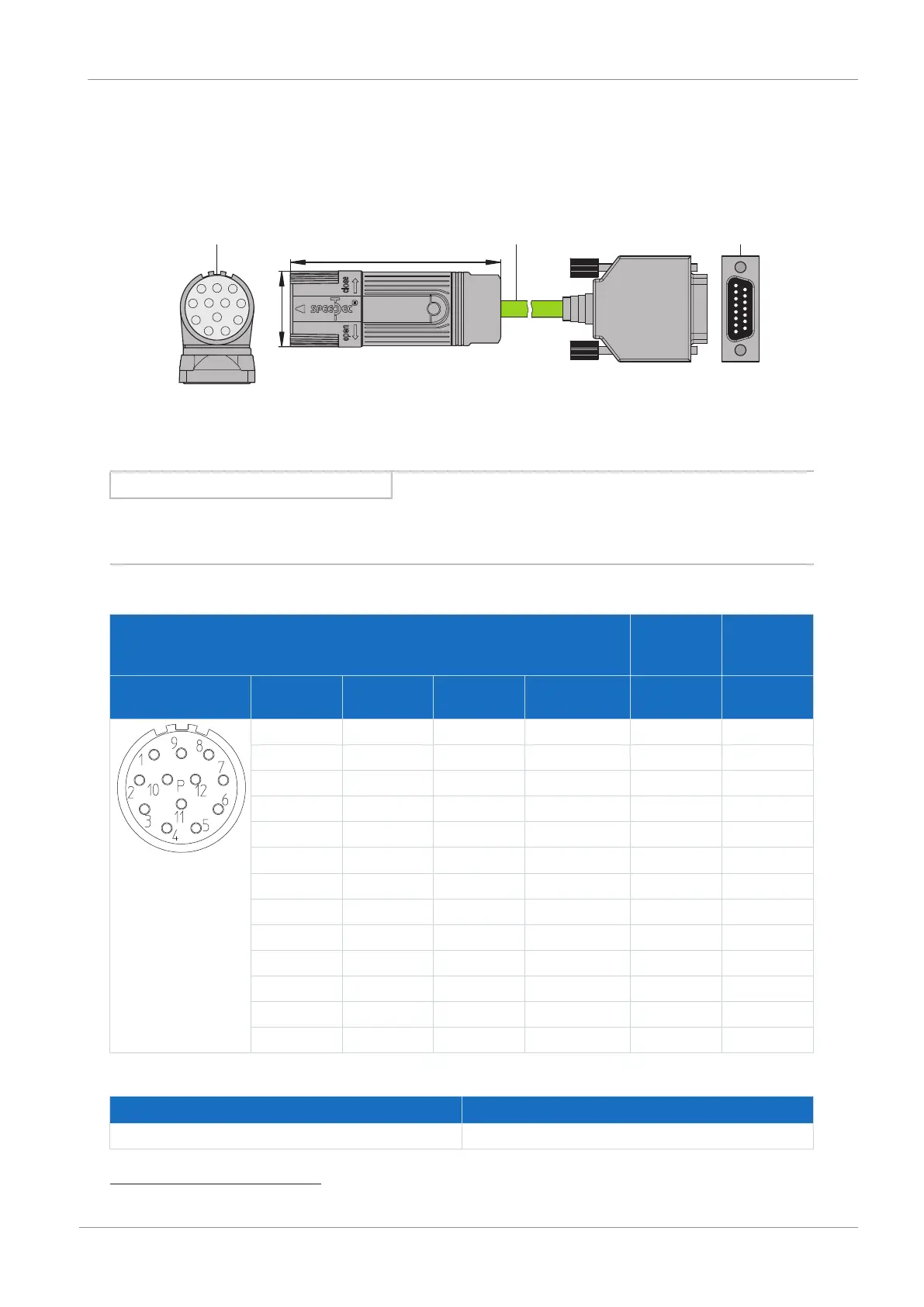
9.6.2.3.1 Connection description
The encoder cable is available in plug connector size con.23 with a speedtec quick lock.
1
3
2
x
y
con.23
1
15
3
1
P
9
2
4
5
8
7
6
10
11
12
1: Plug connectors
2: STOBER encoder cable
3: D-sub X4
Information
For the connection of an HTL incremental encoder to terminal X4 of the SC6 or SI6 drive controller, you need the HT6
adapter (ID No. 56665). HT6 takes over level conversion from HTL signals to TTL signals.
Encoder cables – con.23 plug connector
Motor
(1)
Cable
(2)
Drive
controller
(3)
Connection diagram Pin Designation Core color
up to size 80
Core color
size 90 or larger
Core color Pin
X4
1 B− PK BK YE 9
2 — — YE — —
3 N+ BU PK PK 3
4 N− RD WH GY 10
5 A+ GN GN BN 6
6 A− YE BN WH 11
7 — — — — —
8 B+ GY GY GN 1
9 — — — — —
10 GND WH BU BU 2
17
11 — — VT — —
12 U
2
BN RD RD 4
Housing Shield — — — —
Tab. 120: con.23 encoder cable pin assignment, incremental HTL
Length x [mm] Diameter y [mm]
58 26
Tab. 121: con.23 dimensions
17
Pin 12 (Sense) with pin 2 (GND) bridged: The bridge is constructed in the cable connector that is connected to X4.