STOBER 5 | Technical data
05/2019 | ID 442790.01
33
5.1.2.5 Parallel connection
The charging capacity of the driver controllers can be increased by a parallel connection only if the power grid supply is
connected to all drive controllers simultaneously.
Note the general conditions for parallel connection in the chapter Project configuration [}52].
5.1.2.6 Binary inputs
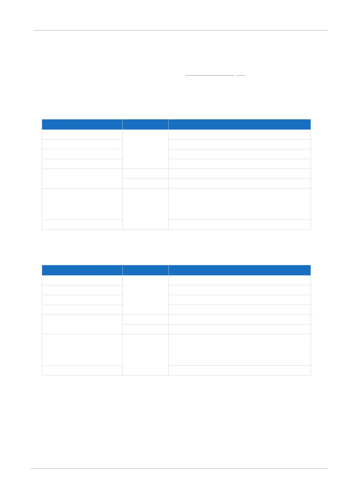
X101 specification for binary signals
Electrical data Binary input Value
Low level BE1 – BE4 0 – 8V
DC
High level 12 – 30V
DC
U
1max
30V
DC
I
1max
16mA
f
1max
BE1 – BE2 10kHz
BE3 – BE4 250kHz
Internal device update rate BE1 – BE4 Cycle time for the application parameterized in A150; t
min
=
1ms;
Also applicable for binary inputs BE3 and BE4: with timestamp
correction in an accuracy range of 1µs
Max. cable length 30m
Tab. 24: X101 electrical data
X103 specification for binary signals
Electrical data Binary input Value
Low level BE6 – BE9 0 – 8V
DC
High level 12 – 30V
DC
U
1max
30V
DC
I
1max
16mA
f
1max
BE6 – BE7 10kHz
BE8 – BE9 250kHz
Internal device update rate BE6 – BE9 Cycle time for the application parameterized in A150; t
min
=
1ms;
Also applicable for binary inputs BE8 and BE9: with timestamp
correction in an accuracy range of 1µs
Max. cable length 30m
Tab. 25: X103 electrical data