STOBER 9 | Connection
05/2019 | ID 442790.01
99
9.5 Braking resistor
Housing grounding of the braking resistor
Note the information on connecting the grounding conductor in the chapter Housing grounding [}77] for the braking
resistor housing ground.
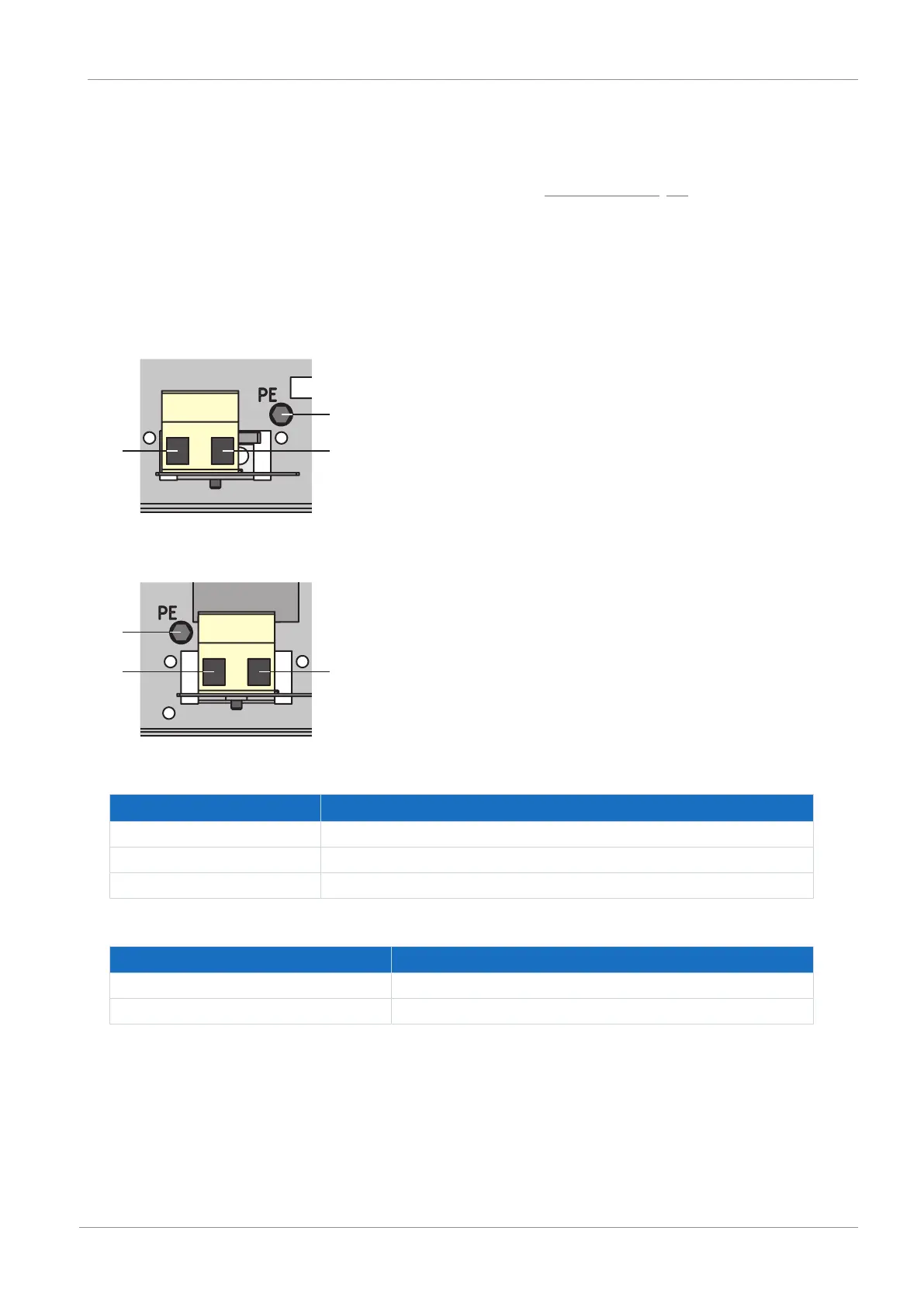
9.5.1 FZMU, FZZMU connection description
The internal connections of the tubular fixed resistor are wired to terminals with heat-resistant, silicone-insulated strands
of wire. Also ensure a heat-resistant and sufficiently surge-proof design for the connection!
Fig.20: FZMU connection overview
Fig.21: FZZMU connection overview
No. Function
1 Grounding conductor connection
2 RB braking resistor drive controller connection: X21, pin 1
3 RB braking resistor drive controller connection: X21, pin 2
Tab. 102: FZMU, FZZMU connection description
Connection type Conductor cross-section [mm²]
Rigid 0.5 – 4.0
Flexible with end sleeve 0.5 – 2.5
Tab. 103: FZMU, FZZMU, FZZMQU conductor cross-section