9 | Connection STOBER
78
05/2019 | ID 442790.01
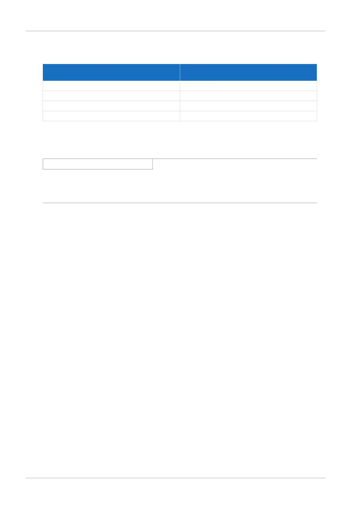
Leakage currents > 10mA can arise in normal operation. To fulfill DIN EN 61800-5-1 and EN 60204-1, connect the grounding
bolt with a copper conductor according to the following table:
Cross-section A
Power grid line
Minimum cross-section A
min
Grounding conductor at grounding bolt
A ≤ 2.5mm² 2.5mm²
2.5 < A ≤ 16mm² A
16 – 35 mm² ≥ 16 mm²
> 35 mm² A/2
Tab. 60: Minimum cross-section of the grounding conductor
9.3.6 EMC recommendations
Information
This chapter provides general information on EMC-compliant installation. These are recommendations. Depending on the
application, the ambient conditions as well as the legal requirements, measures beyond these recommendations may be
required.
Lay the power line, motor cable and signal lines separately from each other, e.g. in separate conduits.
Only use shielded, low-capacitance cables as motor cables.
If the brake line is carried in the motor cable, it must be shielded separately. Also close the brake lines on the drive
controller if you are using a motor without a brake.
Connect the shield of the motor cable over large contact areas and in the immediate vicinity of the drive controller. To do
this, use the shield clamp and shield contact at terminal X20.
The connection lines for braking resistors and the connection lines for Quick DC-Link modules have to be implemented as
twisted pairs. At line lengths of 30cm or more, the lines also have to be implemented with shielding and the shield must be
applied over a wide area in the immediate vicinity of the drive controller.
For motors with terminal boxes, connect the shield to the terminal box over large contact areas. For example, use EMC
cable screw connections.
Connect the shield of the control lines on one side to the reference ground of the source, e.g. the PLC or CNC.