STOBER 9 | Connection
05/2019 | ID 442790.01
97
9.4.22 Connecting a drive controller
DANGER!
Electrical voltage! Risk of fatal injury due to electric shock!
▪ Always switch off all power supply voltage before working on the devices!
▪ Note the discharge time of the DC link capacitors in the general technical data. You can only determine the absence
of voltage after this time period.
Tools and material
You will need:
§ A suitable terminal set for the drive controller
§ Tool for tightening the fastening screws
Requirements and connection
Bottom of the device:
ü
You have a system circuit diagram describing the connection of the drive controller.
1. Optional: Connect the braking resistor to terminal X21 and attach the terminal. Ensure that the connection lines are
twisted pairs.
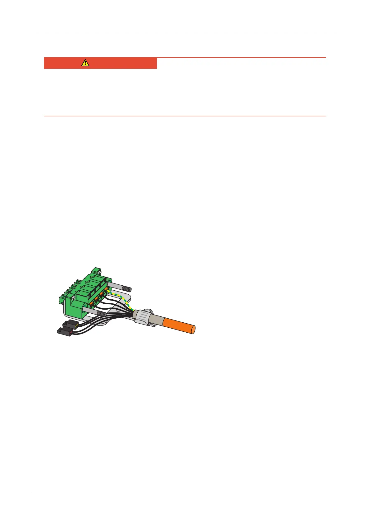
2. In order to connect the motor temperature sensor, the control of the brake and the motor itself to the drive
controller, wire the cores of the power cables with terminals X2A and X20A.
3. Attach the power cable with the shield clamp to the shield contact of terminal X20A.
4. Attach terminals X20A and X2A.
5. Optional: Connect the supply voltage for the brakes to terminal X300 and attach it.
6. For double-axis controllers: Repeat steps 2 to 4 for the terminals X2B and X20B.
7. Optional: Connect an encoder to terminal X4A.
8. Optional for double-axis controllers: Connect an encoder to terminal X4B.