9 | Connection STOBER
92
05/2019 | ID 442790.01
9.4.16 X101: BE1 – BE4
The binary inputs 1 to 4 are available on terminal X101.
X101 for binary signals
For evaluating binary signals at X101, note the specification for the binary inputs in the technical data of the drive
controller, see the chapter Binary inputs [}33].
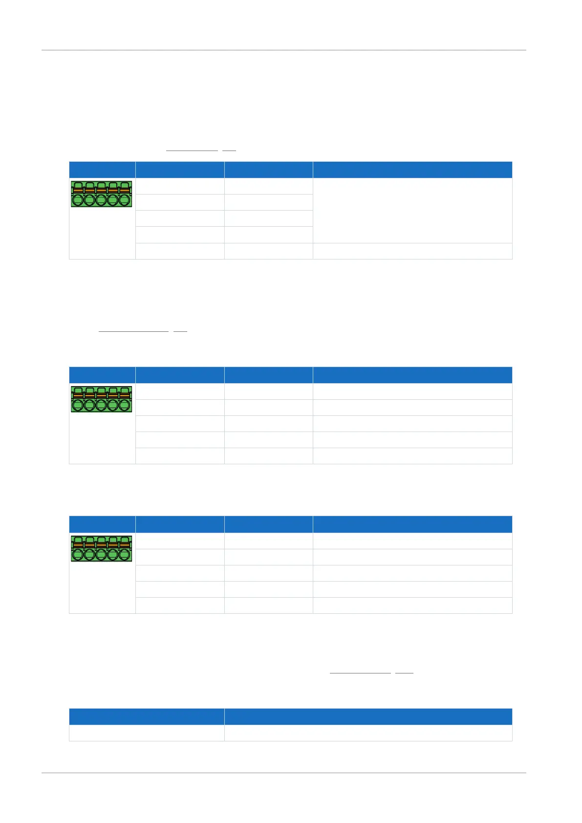
Terminal Pin Designation Function
5|4|3|2|1
1 BE1 Binary inputs
2 BE2
3 BE3
4 BE4
5 DGND Reference ground; not bridged with X103, pin 5
Tab. 89: X101 connection description for binary signals
X101 for encoders
If you would like to use X101 as an encoder connection, note the technical data of the evaluable encoders at X101; see the
chapter X101 for encoders [}46].
Single-ended HTL incremental encoders
Terminal Pin Designation Function
5|4|3|2|1
1 BE1 —
2 BE2 N channel
3 BE3 A channel
4 BE4 B channel
5 DGND Reference ground; not bridged with X103, pin 5
Tab. 90: X101 connection description for single-ended HTL incremental signals, axis A
Single-ended HTL pulse train
Terminal Pin Designation Function
5|4|3|2|1
1 BE1 —
2 BE2 —
3 BE3 Frequency
4 BE4 Direction
5 DGND Reference ground; not bridged with X103, pin 5
Tab. 91: X101 connection description for single-ended HTL pulse/direction signals, axis A
Connecting wiring
For connecting wiring, observe the terminal specifications in the chapter FMC 1,5 -ST-3,5 [}189].
Cable requirements
Feature All sizes
Max. cable length 30m
Tab. 92: Cable length [m]