STOBER 9 | Connection
05/2019 | ID 442790.01
83
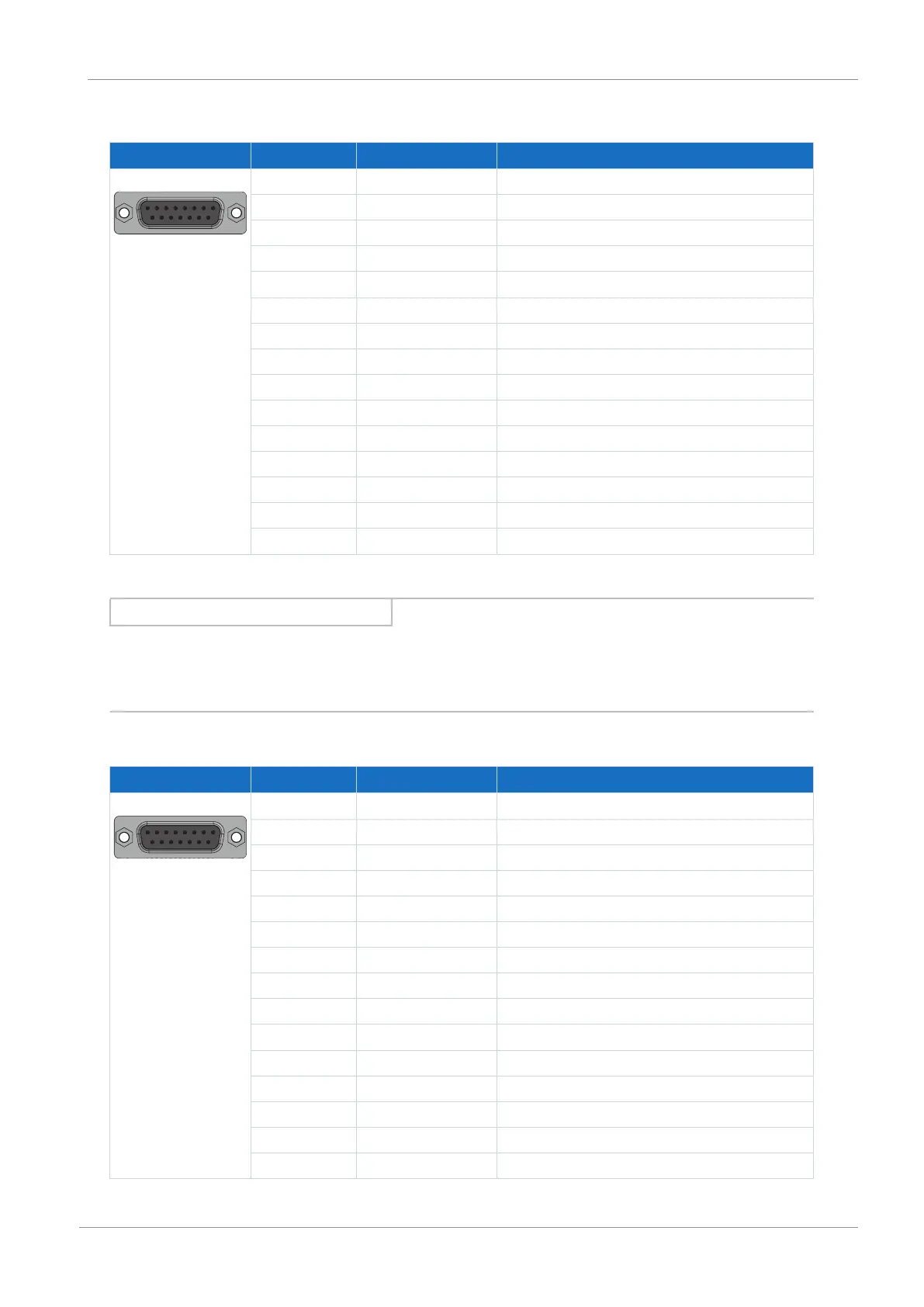
Differential TTL and differential HTL incremental encoders (HTL via HT6 adapter)
Socket Pin Designation Function
8|7|6|5|4|3|2|1
15|14|13|12|11|10|9
1 — —
2 GND Reference potential for encoder supply to pin 4
3 — —
4 U
2
Encoder supply
5 B+ Differential input for B channel
6 — —
7 N+ Differential input for N channel
8 A+ Differential input for A channel
9 — —
10 — —
11 — —
12 — —
13 B− Inverse differential input for B channel
14 N− Inverse differential input for N channel
15 A− Inverse differential input for A channel
Tab. 66: X4A connection description for differential TTL and differential HTL incremental encoders (HTL via HT6 adapter)
Information
Using an HT6 adapter for level conversion from HTL signals to TTL signals, it is also possible to connect a differential HTL
incremental encoder to terminal X4. Note that, with an external power supply, the maximum level of 20V
DC
for the HTL
signals may not be exceeded.
Resolver
Socket Pin Designation Function
8|7|6|5|4|3|2|1
15|14|13|12|11|10|9
1 S4 Sin+ Sin input
2 R1 Ref− Reference potential for pin 6
3 S3 Cos+ Cos input
4 — —
5 — —
6 R2 Ref+ Resolver excitation signal
7 1TP1 Reserve
8 — —
9 S2 Sin− Reference potential for pin 1
10 — —
11 S1 Cos− Reference potential for pin 3
12 — —
13 — —
14 1TP2 Reserve
15 — —
Tab. 67: X4A connection description for resolvers