STOBER 12 | Diagnostics
05/2019 | ID 442790.01
129
12.1.2 FSoE state
If the drive controller includes the SY6 safety module, the STO and SS1 safety functions are activated over EtherCAT FSoE. In
this case, an LED on the front of the device provides information about the state of FSoE communication. This information
can also be read out in parameter S20 FSoE status indicator.
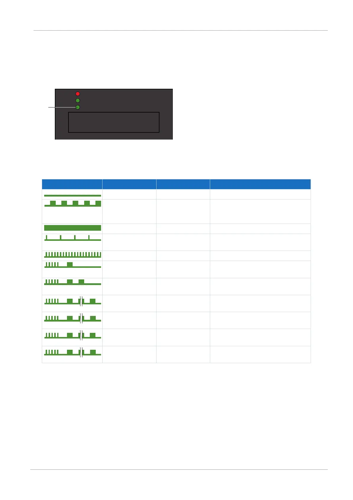
Fig.25: LED for the FSoE state
1 Green: FSoE
Green LED Behavior Possible in FSoE state Description
Off Pre-Reset Initialization
Flashing Reset, session,
connection,
parameters
Ready for parameterization
On Process data Normal operation
Single blink Failsafe data Failsafe command from FSoE master
received
Rapid blinking All Undefined connection error
Rapid blinking with 1x
flash
Parameters Error in the safety-related communication
settings
Rapid blinking with 2x
flash
Parameters Error in the safety-related application
settings
Rapid blinking with 3x
flash
Connection Incorrect FSoE address
Rapid blinking with 4x
flash
All Prohibited command received
Rapid blinking with 5x
flash
All Watchdog error
Rapid blinking with 6x
flash
All CRC error
Tab. 136: Meaning of the green LED (FSoE status indicator in accordance with IEC 61784-3)