STOBER 8 | Installation
05/2019 | ID 442790.01
63
8.3 Minimum clearances
Note the minimum clearances for installation below.
Drive controller
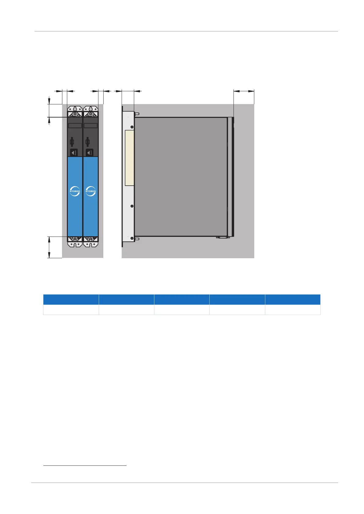
Fig.15: Minimum clearances
The specified dimensions relate to the outer edges of the drive controller.
Minimum clearance A (above) B (below) C (on the side) D (in front)
All sizes 100 200 5 50
7
Tab. 55: Minimum clearances [mm]
Braking resistors
Avoid installation below drive controllers or supply modules. In order for heated air to flow out unimpeded, a minimum
clearance of approximately 200mm must be maintained in relation to neighboring components or walls and approximately
300mm must be maintained to components above or ceilings.
7
Minimum clearance to be taken into account for permanent connection of the X9 service interface