STOBER 5 | Technical data
05/2019 | ID 442790.01
47
5.6 Controllable brakes
The brake of axis A is connected to X2A. Connect the brake of axis B to X2B for double-axis controllers.
You can control the following brakes:
§ Directly connected 24V
DC
brakes
§ Indirectly connected brakes (e.g. over coupling contactor)
The brake is supplied over X300.
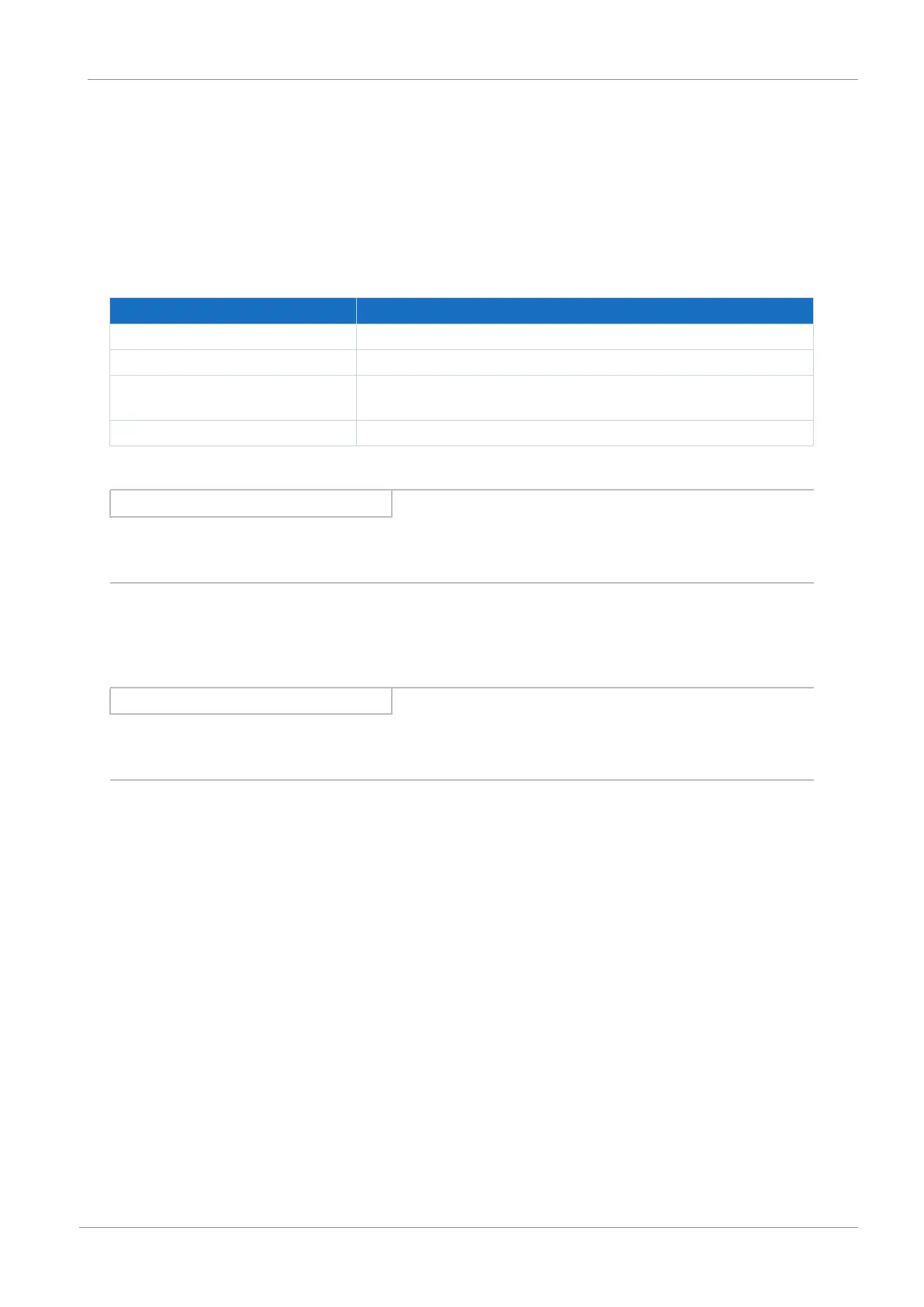
Electrical data Brake output
U
2
24V
DC
, +20%
I
2max
2.5A
f
2max
1Hz at I
N
≤ 2.1A;
0.25Hz at I
N
> 2.1A
E
2max
1.83J
Tab. 48: Electrical data of the brake output
Information
In the case of a nominal brake current > 2.1A, the system controller must ensure compliance with the maximum switching
frequency of 0.25Hz.
5.7 Evaluable motor temperature sensors
You can connect a maximum of 2 PTC triplets in series to the SC6 drive controller.
Information
Note that temperature sensor evaluation is always active. If operation without a temperature sensor is permitted, the
connections must be bridged on X2. Otherwise a fault is triggered when switching on the device.