STOBER 6 | Project configuration
05/2019 | ID 442790.01
57
6.4 Mixed operation
You can combine the SC6 drive controller with other drive controllers from the 6th generation of STOBER drive controllers.
In mixed operation, only device types of the same series may be supplied with power. The framework conditions for the
supplying device apply.
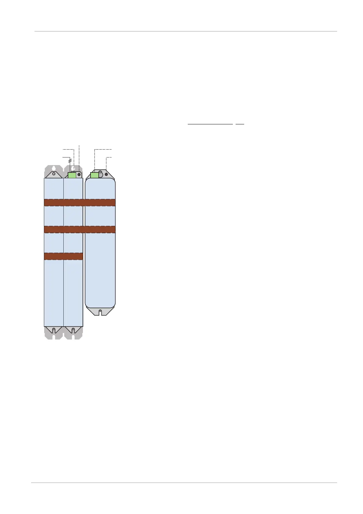
The graphic below shows an example of the grounding concept in mixed operation with SI6 and SD6 with power from an
SC6 drive controller. The protective connection between the drive controller and the associated Quick DC-Link rear section
module (type DL6B or DL6A) is made using the metallic connection of the housings. The protective connection between the
rear section modules of the DL6B type is made using a copper rail. You can find the requirements for the connection of a
2nd grounding conductor for the drive controllers in the chapter Housing grounding [}77].
DC+
DC−
PE
SI6
DL6B
SC6
DL6B
SD6
DL6A
1. PE
2. PE
X10
1. PE
2. PE
X10
Fig.11: Grounding concept in mixed operation with SI6 and SD6 with powered SC6 drive controller
If the protective connection over the 3rd copper rail is omitted between DL6B rear section modules, the SI6 drive
controllers must be grounded on the bottom of the housing. A PE symbol is there on the fastening clip.