STOBER 9 | Connection
05/2019 | ID 442790.01
85
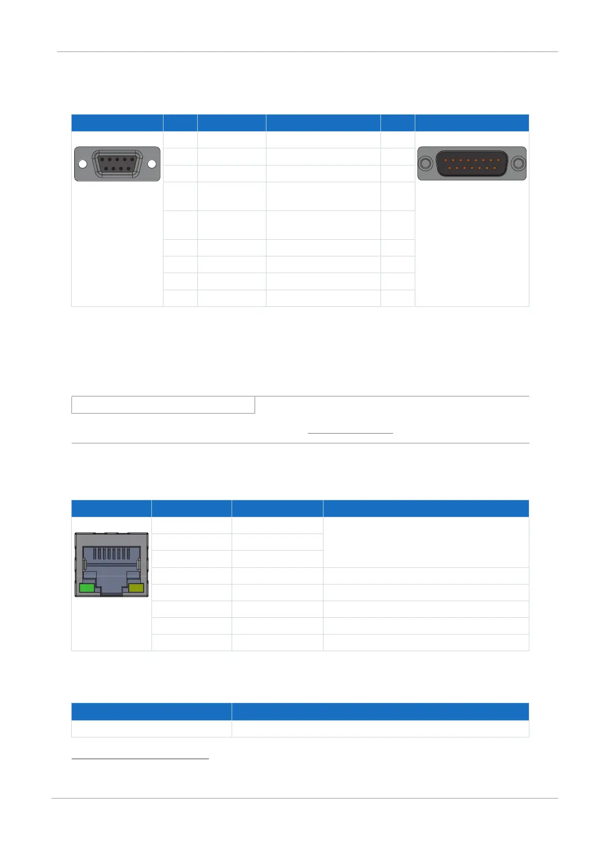
9.4.6.1 AP6 interface adapter (resolver)
AP6A00 – resolver (9-pin to 15-pin)
Socket
8
Pin Designation Function Pin Connector
9
1 | 2 | 3 | 4 | 5
6 | 7 | 8 | 9
1 — — — 1|2|3|4|5|6|7|8|9
10|11|12|13|14|15
2 1TP1 — —
3 S2 Sin− Sin input reference potential 9
4 S1 Cos− Cos input reference
potential
11
5 R1 Ref− Resolver excitation signal
reference potential
2
6 1TP2 — —
7 S4 Sin+ Sin input 1
8 S3 Cos+ Cos input 3
9 R2 Ref+ Resolver excitation signal 6
Tab. 71: AP6A00 connection description for resolver (9-pin to 15-pin)
9.4.7 X4B: Encoder B
The encoder of axis B is connected to X4B for double-axis controllers. Only X4A is available for single-axis controllers. The
connection description of X4B matches the X4A description.
Information
Note that a master encoder must be connected to axis A during synchronous operation.
9.4.8 X9: Ethernet service interface
X9 is used to connect the drive controller to a PC with DriveControlSuite commissioning software installed.
Socket Pin Designation Function
1|2|3|4|5|6|7|8 1 TxData+ Ethernet communication
2 TxData−
3 RecvData+
4 — —
5 — —
6 RecvData− Ethernet communication
7 — —
8 — —
Tab. 72: X9 connection description
Cable requirements
Feature All sizes
Max. cable length 100m, shielded
Tab. 73: Cable length [m]
8
View of 9-pin D-sub for connecting the SDS 4000-compatible resolver cable
9
View of 15-pin D-sub for connecting to terminal X4