STOBER 9 | Connection
05/2019 | ID 442790.01
113
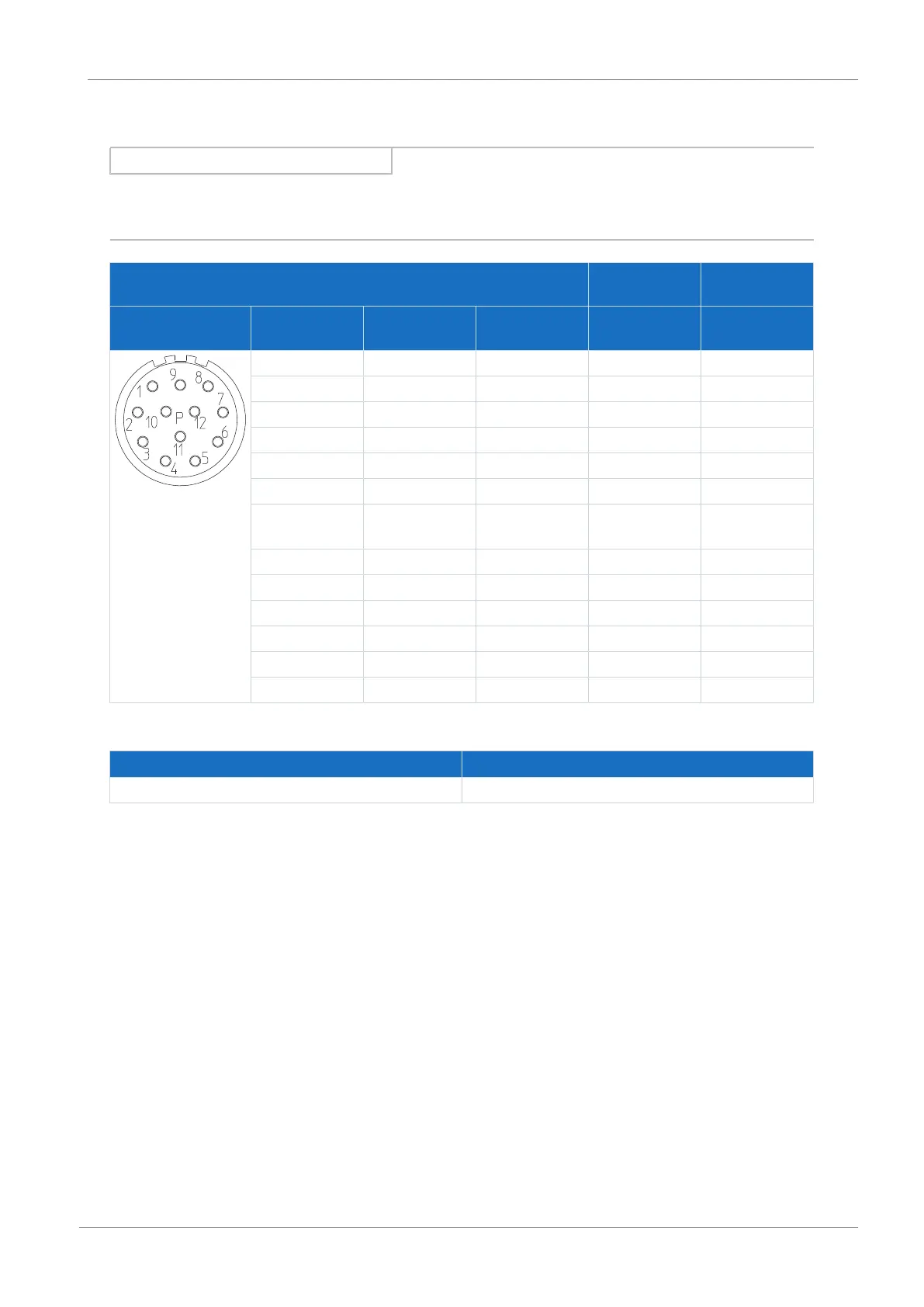
Encoder cables – con.23 plug connector
Information
For connecting STOBER resolver cables with a 9-pin D-sub connector, you also require the AP6A00 interface adapter (ID No.
56498, 9-pin to 15-pin D-sub), available separately.
Motor
(1)
Cable
(2)
Drive controller
(3)
Connection diagram Pin Designation Core color Core color Pin
X4
1 S3 Cos+ BK YE 3
2 S1 Cos− RD GN 11
3 S4 Sin+ BU WH 1
4 S2 Sin− YE BN 9
5 1TP1 BK RD —
6 1TP2 WH BU —
7 R2 Ref+ YEWH/
BKWH
GY 6
8 R1 Ref− RDWH PK 2
9 — — — —
10 — — — —
11 — — — —
12 — — — —
Housing Shield — — —
Tab. 126: con.23 encoder cable pin assignment
Length x [mm] Diameter y [mm]
58 26
Tab. 127: con.23 dimensions