STOBER 9 | Connection
05/2019 | ID 442790.01
79
9.4 Drive controller
The following section contains detailed information about the terminals and the correct connection of the drive controller.
9.4.1 Overview
1
3
2
4
5
7
6
8
5
3
4
2
1
X103
X101
3
6
7
8
5
X201
X200
5
3
4
2
1
X11
1
L2
L1
L3
PE
2
X10
4
X12
13
16
11
12
14
15
86
5
7
X22
X20A
X2A
X2B
X20B
8
7
9
10
D
D
X4A
X4B
PE
V
W
U
PE
V
W
U
6
5
X300
17
X21
RB
RB
15
17
18
16
X700
X9
1
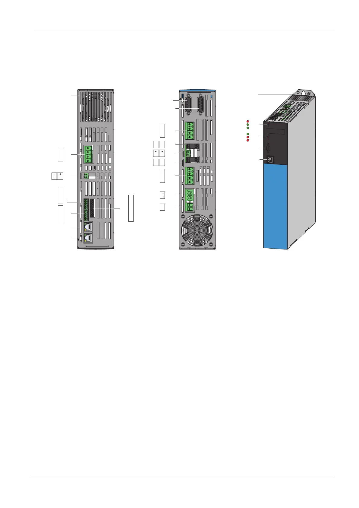
Fig.19: Connection overview using the example of the SC6A162
Top of the device Bottom of the device Front of the device
1 Ground bolt 9 X4B: Encoder B (only for double-axis
controllers)
18 3 diagnostic
LEDs for communication and
safety technology
2 X10: 400V
AC
supply 10 X4A: Encoder A 19 3 diagnostic LEDs for drive
controller
3 X11: 24V
DC
supply 11 X20B: Motor B (only for double-axis
controllers)
20 X700: SD slot
4 X10³: BE6 – BE9 12 X2B: Brake B (pin 5/6)
andtemperature sensor B (pin 7/8);
(only for double-axis controllers)
21 X9: Ethernet service interface
5 X12: STO via terminals (only for
SR6 option)
13 X300: Brake 24V
DC
supply
6 X101: BE1 – BE4 14 X2A: Brake A (pin 5/6)
andtemperature sensor A (pin 7/8)
7 X201: EtherCAT Out/ PROFINET 15 X20A: Motor A
8 X200: EtherCAT In/ PROFINET 16 X22: DC link connection
17 X21: Braking resistor