8 | Installation STOBER
70
05/2019 | ID 442790.01
Requirements and installation
Perform the following steps for each drive controller within the group.
ü
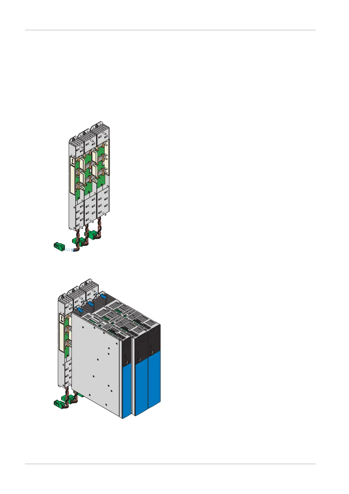
There is a circuit diagram of the system that describes the connection of the drive controllers.
ü
For each drive controller, the appropriate DL6B Quick DC-Link rear section modules for the DC link connection have
already been installed in the installation position.
1. Remove terminal X22 from the appropriate terminal set. Connect the brown cable D+ on the bottom of the Quick DC-
Link module to D+ of terminal X22, and the black cable D- of the Quick DC-Link module to D- of terminal X22. Ensure
that the connection lines of the Quick DC-Link module are twisted pairs.
2. Place the drive controller on the bottom threaded bolt of the Quick DC-Link module and properly align it vertically
with the bottom and top threaded bolt.