ELECTRICAL SYSTEM 10-27
FUEL METER
• Remove the trunk box. (9-16)
• Connect each resistor between the Red/Black and Black/
White lead wires at the wire harness.
• Turn the ignition switch “ON” position and wait for approx. 13
seconds.
Check the display of fuel meter as shown below, If any abnor-
mality is found, replace the combination meter with a new one.
FUEL GAUGE
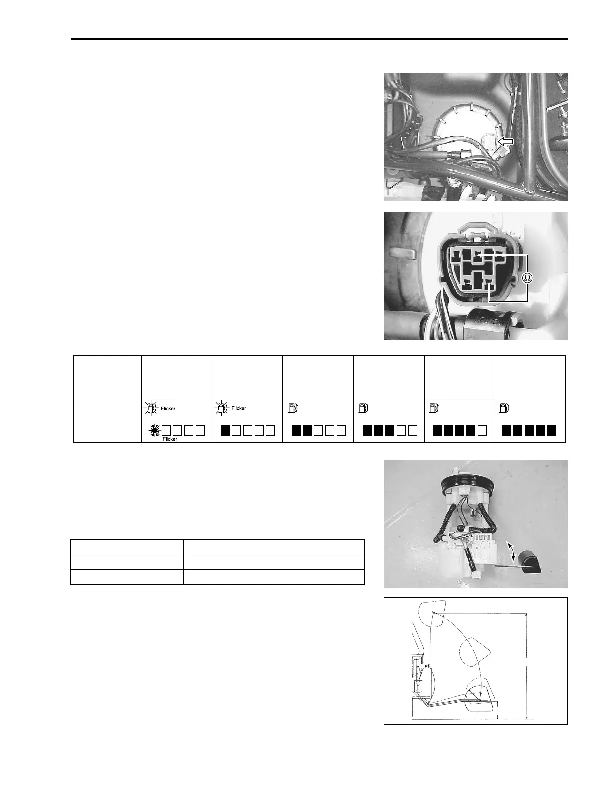
• Remove the fuel pump. (7-7)
Measure the resistance at each fuel level gauge float position. If
the resistance is incorrect, replace the fuel level gauge with a
new one.
[ 09900-25008: Multi circuit tester set
U Tester knob indication: Resistance (Ω
ΩΩ
Ω)
Resistance
More than
112 Ω
Less than
50 Ω
96 – 112 Ω
82 – 96 Ω
71 – 82 Ω 51 – 62 Ω
Fuel level
meter
EFEFEFEFEFEF
– ON– ON – ON – ON
Float position Resistance
A “F” (Full) Approx. 13 Ω
B “E” (Empty) Approx. 130 Ω
E
F
22 mm
130 mm

 Loading...