10-30 ELECTRICAL SYSTEM
SPEEDOMETER SENSOR
• Remove the final gear case cover. (2-15)
• Remove the left frame cover. (9-16)
• Disconnect speedometer sensor coupler
1.
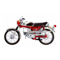
• Remove the speedometer sensor
2 by removing its mounting
bolt and lead wire set bolts.
Connect 12 V battery, 10 kΩ resistor and the multi circuit tester
as shown in the right illustration.
O/R: Orange with Red tracer
B/W: Black with White tracer
W: White
[ 09900-25008: Multi circuit tester set
V Tester knob indication: Voltage (
)
Under above condition, if a suitable screwdriver touching the
pick-up surface of the speedometer sensor is moved, the tester
reading voltage changes (0 V → 12 V or 12 V → 0 V). If the
tester reading voltage does not change, replace the speedome-
ter sensor with a new one.
NOTE:
The highest voltage reading in this test will be the same as that
of battery voltage (12 V).
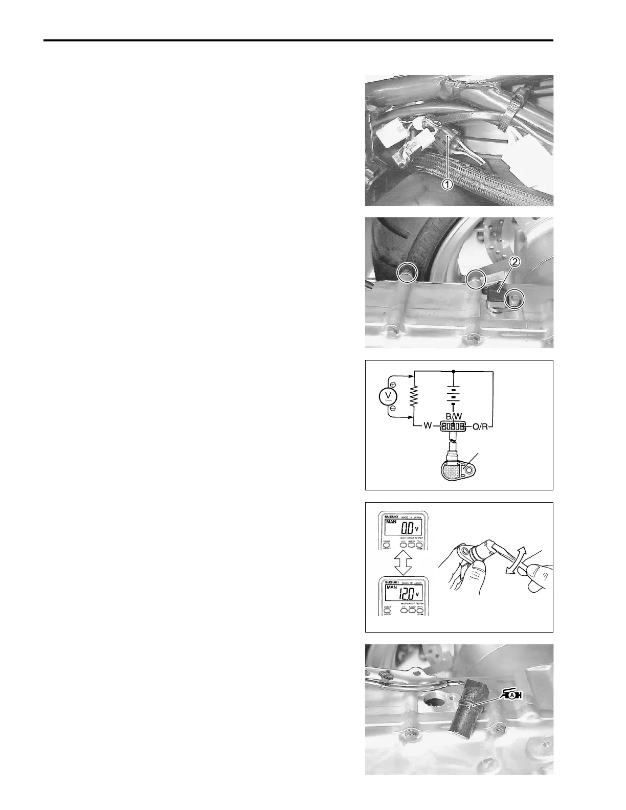
• Apply SUZUKI SUPER GREASE “A” to the speed sensor O-
ring before installing it.
W 99000-25030: SUZUKI SUPER GREASE “A” (USA)
99000-25010: SUZUKI SUPER GREASE “A” (Others)
Speedometer sensor
12 V
10 kΩ
(Battery voltage)

 Loading...