12-6 FI SYSTEM DIAGNOSIS
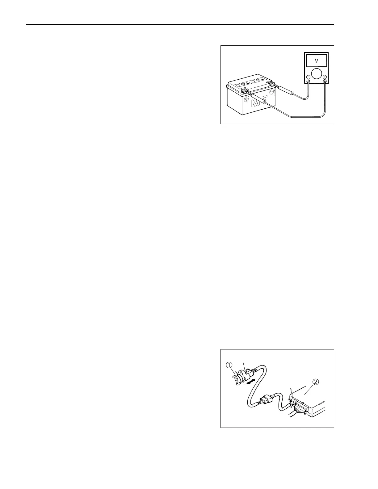
• Before measuring voltage at each terminal, check to make
sure that battery voltage is 11 V or higher. Terminal voltage
check with a low voltage battery will lead to erroneous diagno-
sis.
• Never connect any tester (voltmeter, ohmmeter, or whatever)
to the ECM when its coupler is disconnected.
Otherwise, damage to ECM may result.
• Never connect an ohmmeter to the ECM with its coupler con-
nected. If attempted, damage to ECM or sensors may result.
• Be sure to use a specified voltmeter/ohmmeter. Otherwise,
accurate measurements may not be obtained and personal
injury may result.
ELECTRICAL CIRCUIT INSPECTION
PROCEDURE
While there are various methods for electrical circuit inspection,
described here is a general method to check for open and short
circuit using an ohmmeter and a voltmeter.
OPEN CIRCUIT CHECK
Possible causes for the open circuits are as follows. As the
cause can exist in the connector/coupler or terminal, they need
to be checked carefully.
• Loose connection of connector/coupler.
• Poor contact of terminal (due to dirt, corrosion or rust, poor
contact tension, entry of foreign object etc.).
• Wire harness being open.
• Poor terminal-to-wire connection.
• Check each connector/coupler at both ends of the circuit
being checked for loose connection. Also check for condition
of the coupler lock if equipped.
1 Sensor
2 ECM
*1 Check for loose connection.
*1
*1

 Loading...


