FI SYSTEM DIAGNOSIS 12-37
Step 1 (When indicating P0115-L:)
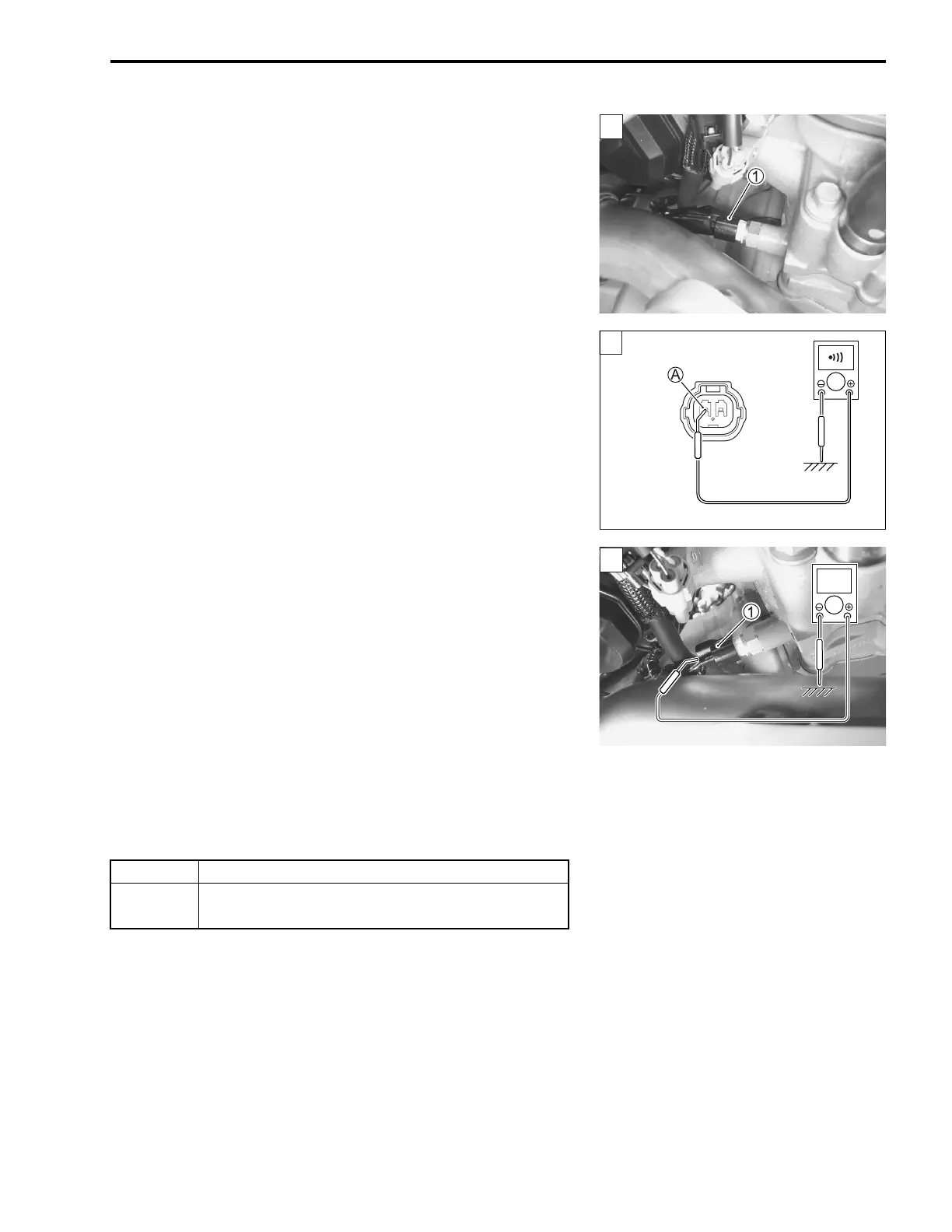
1) Stop the engine.
2) Check the ECT sensor coupler 1 for loose or poor contacts.
If OK, then measure the output voltage.
3) Remove the fuel tank. (13-2, -3)
4) Disconnect the ECT sensor coupler and ECM coupler.
5) Insert the needle-pointed probes to the lead wire coupler.
6) Check the continuity between B/Bl wire A and ground.
If the sound is not heard from the tester, the circuit condition
is OK.
Tester knob indication: Continuity test ()
7) Connect the ECT sensor coupler 1 and ECM coupler.
8) Insert the needle-pointed probe to the lead wire coupler.
9) Connect a 12 volts battery by using the battery lead wire to
the service coupler. (12-19)
10)Measure the voltage between B/Bl wire and ground.
ECT sensor output voltage: 0.20 – 4.90 V
(+ B/BI – - Ground)
09900-25008: Multi circuit tester set
09900-25009: Needle-pointed probe set
36890-28H00: Battery lead wire (option)
Tester knob indication: Voltage ()
Are the continuity and voltage OK?
1
1
YES Go to Step 2.
NO
• B/BI wire shorted to ground.
• If wire is OK, go to Step 2.
1
V

 Loading...


