!
16
Caution The following instructions cannot be used when the CQM1-CPU43-EV1 is set to
high-speed counter mode by PC Setup (DM 6611): PLS2 and ACC mode 0.
LED Indicators
Ready (green)
Lit when the pulse I/O function is ready.
Error (red)
Lit when there is an error in the PC Setup for the pulse I/O func-
tion, or when operation is interrupted during pulse output.
RDY ERR CW1
CCW1
CW2
CCW2
A2
B2
Z2
A1
B1
Z1
Pulse output (orange)
Refer to the table below.
Pulse input (orange)
Refer to the table below.
Indicator Port Function
CW1
Port 1
Lit during pulse output to port 1 CW.
CCW1 Lit during pulse output to port 1 CCW.
CW2
Port 2
Lit during pulse output to port 2 CW.
CCW2 Lit during pulse output to port 2 CCW.
Port 1 Port 2 Function
A1 A2 Lit when pulse input is ON at phase A for each port.
B1 B2 Lit when pulse input is ON at phase B for each port.
Z1 Z2 Lit when pulse input is ON at phase Z for each port.
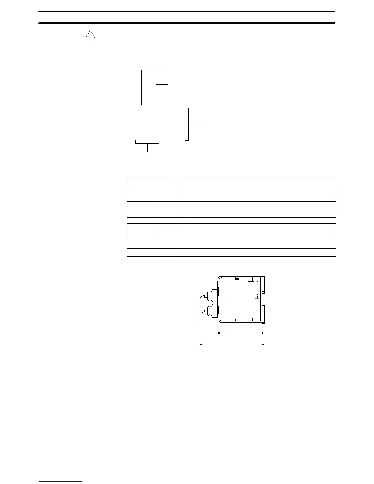
Dimensions With Connectors Mounted
107 mm
Approx. 180 mm
Pulse Output Indicators
Pulse Input Indicators
CPU Unit Section 2-1