30
Leakage Current (24 VDC) A leakage current can cause false inputs when using 2-wire sensors (proximity
switches or photoelectric switches) or limit switches with LEDs on 24 VDC.
If the leakage current exceeds 1.3 mA, insert a bleeder resistor in the circuit to
reduce the input impedance, as shown in the following diagram.
R
SYSMAC
Input power
supply
Bleeder resistor
2-wire method
sensor, etc.
R = 7.2/(2.4I–3) kΩ max.
W = 2.3/R W min.
I: Device’s leakage current (mA)
R: Bleeder resistance (kΩ)
W: Bleeder resistor’s power rating (W)
The equations above were derived from the following equation:
W ≥ Input voltage (24)/R Input voltage (24) tolerance (4)
I
R
Input voltage (24)
Input current (10)
R +
Input voltage (24)
Input current (10)
≤ OFF voltage (3)
Inrush Current The following diagram shows two methods that can be used to reduce the large
inrush current caused by certain loads, such as incandescent light bulbs.
R
OUT
COM
OUT
COM
R
Example 1 Example 2
Generating a dark current (about 1/3 of the
rated current) through the incandescent bulb.
Inserting a regulating resistance.
Be careful not to damage the output transistor.
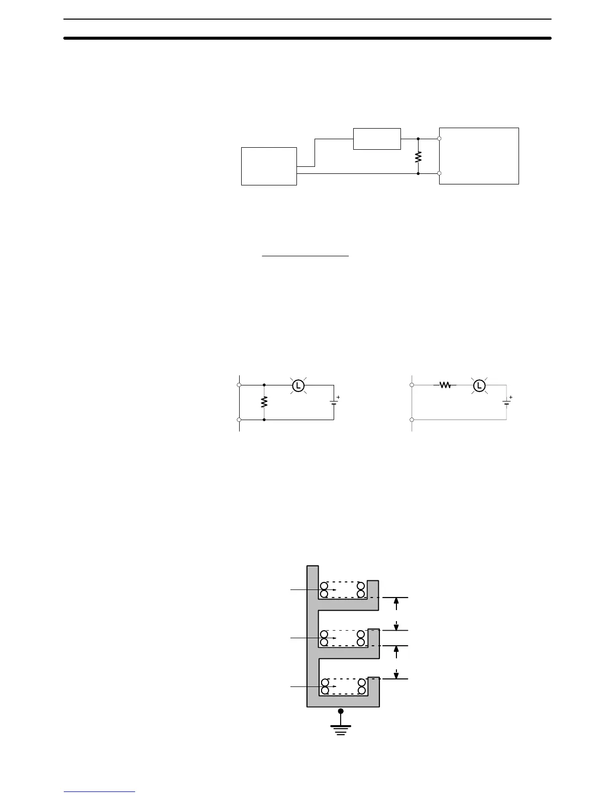
I/O Line Noise Do not run CQM1 I/O lines in the same duct or conduit as multi-conductor cables
of other control lines. If power cables carry more than 10 A at 400 V or more than
20 A at 220 V, they must be run parallel to I/O wiring. Leave at least 300 mm
between the power cables and the I/O wiring, as shown in the following diagram.
Low current cables
Control cables and
CQM1 power lines
Power cables
300 mm min.
300 mm min.
Grounding at resistance
of 100 W
max.
Wiring and Connections
Section 2-5