!
49
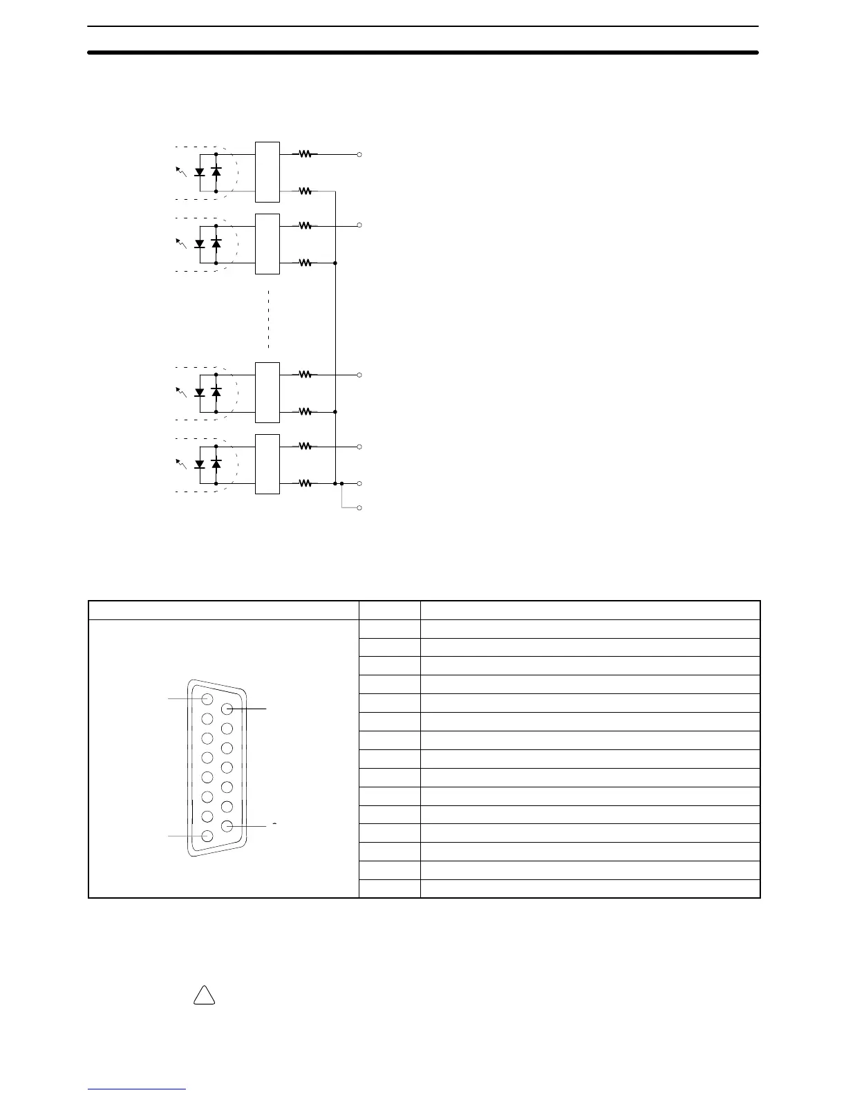
Internal Circuit Configuration
Bit no. Name
2 Encoder input Grey code 2
11
bit. . . . .
2.7 kΩ
2.7 kΩ
2.7 kΩ
2.7 kΩ
2.7 kΩ
2.7 kΩ
2.7 kΩ
2.7 kΩ
10 Encoder input Grey code 2
10
bit. . . .
7 Encoder input Grey code 2
1
bit. . . . .
15 Encoder input Grey code 2
0
bit. . . .
1 Input common. . . . .
9 Input common. . . . .
Connector Pin Arrangement
Pin arrangement Pin no. Signals
1 Input common
2 Encoder input, grey code 2
11
bit
3 Encoder input, grey code 2
9
bit
4 Encoder input, grey code 2
7
bit
8
15
5 Encoder input, grey code 2
5
bit
6 Encoder input, grey code 2
3
bit
7 Encoder input, grey code 2
1
bit
8 NC
9 Input common
10 Encoder input, grey code 2
10
bit
11 Encoder input, grey code 2
8
bit
1
9
12 Encoder input, grey code 2
6
bit
13 Encoder input, grey code 2
4
bit
14 Encoder input, grey code 2
2
bit
15 Encoder input, grey code 2
0
bit
Note Ports 1 and 2 are the same.
Caution The only absolute-type encoder that can be connected is the grey binary code
output type.
Unit Specifications
Section 2-6