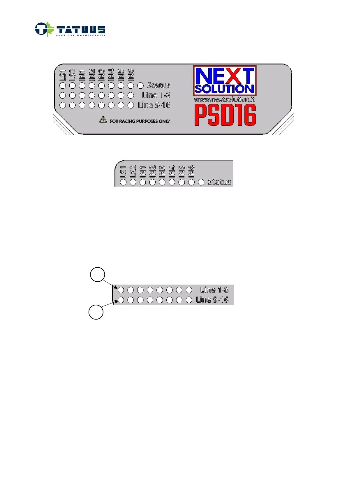
The powerbox features an on board led indicator panel. Please find it reported in picture below
First row led strip
• LS1, LS2 : not used
• IN1 – IN6: show the status of the input activation. With reference to paragraph Error! Reference
source not found. when the main switch is ON, the led “IN6” turns on; when IGNITION switch is
ON, the led “IN6” and the led “IN3” turn on
• Status: turns on when the power box is powered. Please note: when the Jump battery is plugged in
and the main switch is OFF, the status led blinks.
Second and third row led strips
• Line 1-8 and Line 9-16: show the status of the relevant line. To understand which function is
associated to each line, please refer to the first column (“PSD line numbering”) in the connection
map in the next page. The led is normally green or blue. If the led is red, it indicates the relevant
line has been cut due to overcurrent detected.



 To Next Page