11.4 ELECTRICAL SCHEMATICS
Refer to PDF files available in the Tatuus’ sharezone for electrical schematics.
11.4.1 Radio plug
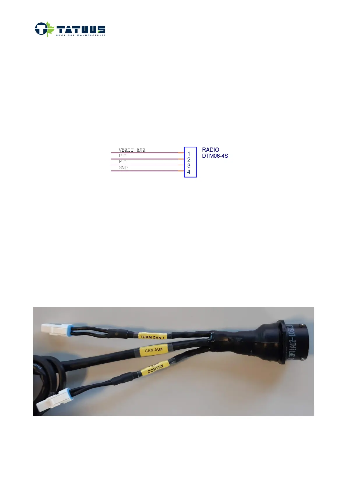
A radio connector is provided in the chassis wiring, it provides a 12V power and repeat the switch of the
steering wheel on pins #2/#3.
Mating connector DTM04-4P.
11.4.2 CAN lines
The system architecture feature 3 CAN lines.
• CAN 0: system dedicated is used to connect ECU, GCU, Steering wheel.
• CAN 1: dedicated CAN line for "federation" devices: RAIN Light, ADR.
• CAN Cortex: "user" can. It is used by low priority devices.
Can auxiliary connection and can terminations are available on:
• Chassis loom: located in the cockpit beside the fire extinguisher bottle
• Gearbox loom: located on the top rear end of the gearbox. Please remind the gearbox loom is
equipped with connectors for the Endplate lights that are compatible with can termination ones. Pay
attention to not invert them.
Please find below a picture showing the Auxiliary can connector and CAN termination connection.


 To Next Page