k.
CHECK-CRT display for optimum
square-wave
re-
sponse similar to Channel 1 response (see Fig. 5-178).
I.
ADJUST-R149,
Cl49,
C154,
and
C145A (see Fig.
5-17C) for optimum
square-wave
response similar to Chan-
nel 1 response. Repeat this adjustment until optimum re-
sponse
is
obtained.
NOTE
If
response
of
Channel
1
and
2
cannot
be
cor-
rectly
matched
using
this
adjustment
procedure,
see
the
procedure
for
reselecting
Rl
95
given
in
Table
5-4.
m.
Set
the
CH
2
VOL
TS/DIV switch to 10
mV.
n.
Set
the
square-wave
generator
for a four-division dis-
play.
o.
CHECK-CRT
display for optimum
square-wave
re-
sponse (see Fig. 5-178).
p. ADJUST-R144C,
Cl44C,
and
C144A,
in
given
order,
(see Fig. 5-l 7C) for optimum
square-wave
response. Repeat
this adjustment until optimum response
is
obtained.
q. Set the
CH
2
VOL
TS/DIV switch to 5
mV.
r.
Set the
square-wave
generator
for a four-division dis-
play.
s.
CHECK-CRT display for optimum
square-wave
re-
sponse (see Fig. 5-178).
Performance
Check/Calibration-Type
453/R453
t.
ADJUST-Rl43C,
Cl43C,
Cl43A,
and
L143A
(see Fig.
5-17C) for optimum
square-wave
response. Repeat this
ad-
justment until optimum response
is
obtained.
u.
Change
the following control settings:
MODE
CH
l VOLTS/DIV
CH
l
SmV
v.
Disconnect the 50-ohm in-line termination from the
Channel 2 INPUT connector
and
connect
it
to the Channel
l
INPUT
connector.
w. CHECK-CRT display for optimum
square-wave
re-
sponse (see Fig. 5-178).
x. ADJUST-R43C, C43C, C43A,
and
L43A
(see Fig. 5-17C)
for optimum
square-wave
response. Repeat this adjustment
until optimum response
is
obtained.
y.
Set the
CH
1 VOLTS/DIV switch to 10
mV.
z. Set the
square-wave
generator
for a four-division dis-
play.
aa.
CHECK-CRT display for optimum
square-wave
re-
sponse (see Fig. 5-178).
ab.
ADJUST-R44C, C44C, C44A, (see
Fig.
5-17C) for
optimum
square-wave
response. Repeat this adjustment
until optimum response
is
obtained.
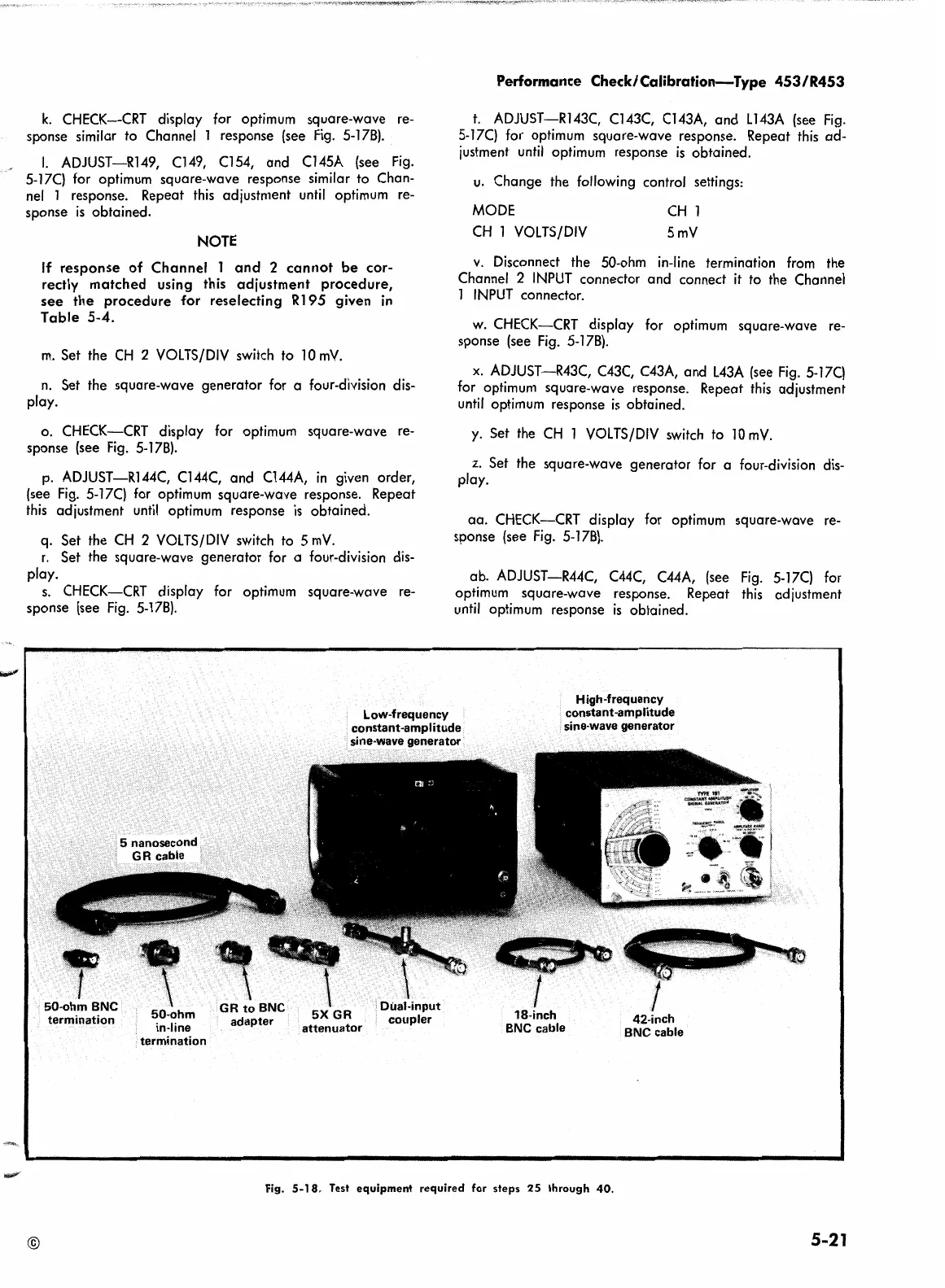
Low-frequency
constant-amplitude
sine-wave generator
High-frequency
constant-amplitude
sine-wave generator
©
•
1
50-ohm
BNC
termination
50-ohm
in-line
termination
GR
to
BNC
adapter
5XGR
attenuator
Fig.
5-18.
Test
equipment
required
for
steps
25
through
40.
42-inch
BNC
cable
5-21
 Loading...


