Performance
Check/Calibration-Type 453/R453
CONTROL
SETTINGS
Set
the
controls
as
given under Preliminary Control
Settings
except
as
follows:
INTENSITY
FOCUS
A and B
TIME/DIV
A
SWEEP
MODE
Midrange
Adjust for a focused
display
20
µs
AUTO
TRIG
25.
Check
Upper Vertical Bandwidth
Limit
of
Channel 1 and 2
a. Test equipment required for steps
25
through 40
is
shown
in
Fig.
5-18.
b.
Connect the constant-amplitude sine-wave generator
(Type
191)
to the Channel l
INPUT
connector through the
five-nanosecond
GR
cable, 5 X
GR
attenuator and the 50-
ohm
in-line termination.
c.
Set the constant amplitude generator for a four-divi-
sion display
at
its
reference frequency
(50
kHz).
d. Without changing the output amplitude, increase the
output frequency of the generator
until
the deflection
is
reduced to
2.8
divisions
(-3
dB
point; see
Fig.
5-19).
e. CHECK-Output frequency of generator
must
be
50
megahertz or higher.
f.
Set the
CH
l
VOLTS/DIV
switch to
10
mV.
g. Set the constant-amplitude generator for Q four division
display
at
its
reference frequency
(50
kHz).
h.
Without changing the output amplitude, increase the
output frequency of the generator
until
the deflection
is
reduced to 2.8 divisions
(-3
dB
point; see
Fig.
5-19).
i.
CHECK-OutP.ut frequency of generator must be
45
megahertz or higher.
I·
Set the
CH
l
VOLTS/DIV
switch to 5
mV.
k.
Set the constant-amplitude generator for a four divi-
sion display
at
its
reference frequency
(50
kHz).
I.
Without changing the output amplitude, increase the
output frequency of the generator
until
the deflection
is
reduced to
2.8
divisions
(-3
dB
point; see
Fig.
5-19).
m.
CHECK-Output frequency of generator
must
be
40
megahertz or higher.
n.
Set the
MODE
switch to
CH
2.
o. Disconnect the output of the in-line termination
from
the Channel 1
INPUT
connector and connect
it
to the Chan-
nel
2
INPUT
connector.
p.
Set the constant-amplitude generator for a four-divi-
sion display
at
its
reference frequency
(50
kHz).
q.
Without changing the output amplitude, increase the
output frequency of the generator
until
the deflection
is
reduced to
2.8
divisions
(-3
dB
point; see
Fig.
5-19).
5-22
r.
CHECK-
Output frequency of generator must be 50
megahertz or higher. ..-
s.
Set the
CH
2
VOLTS/DIV
switch to 10
mV.
t.
Set the constant-amplitude generator for a four-division
display
at
its
reference frequency
(50
kHz).
u.
Without changing the output amplitude, increase the
output frequency of the generator
until
the deflection
is
re-
duced to
2.8
divisions
(-3
dB
point; see
Fig.
5-19).
v.
CHECK-Output frequency of generator
must
be
45
megahertz or higher.
w.
Set the
CH
2
VOLTS/DIV
switch to 5
mV.
x.
Set the constant-amplitude generator for a four-divi-
sion display
at
its
reference frequency
(50
kHz).
y.
Wit.hout changing the output amplitude, increase the
output frequency of the generator
until
the deflection
is
re-
duced to
2.8
divisions
(-3
dB
point; see
Fig.
5-19).
z.
CHECK-Output frequency of generator must· be
40
megahertz or higher.
26.
Check
Added Mode Upper Bandwidth
Limit
a. Change the following control settings:
VOL
TS/DIV
(CH
1 and
2)
20
mV
CH
l POSITION
CH
1 Input Coupling
MODE
Midrange
GND
ADD
b.
Set the constant-amplitude generator for a four-division
display
at
its
reference frequency
(50
kHz).
c.
Without changing the output amplitude, increase the
output frequency of the generator
until
the deflection
is
reduced to 2.8 divisions
(-3
dB
point; see
Fig.
5-19).
d.
CHECK-Output frequency of generator
must
be 50
megahertz or higher.
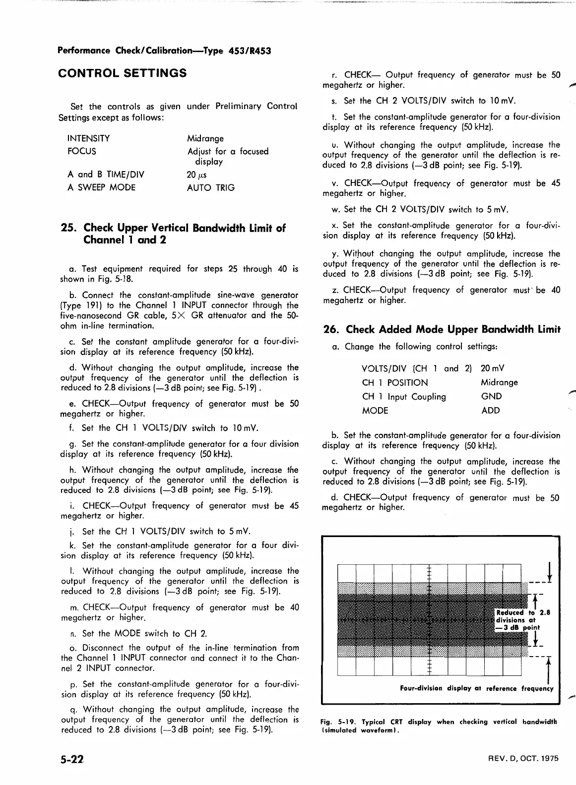
Four-division
display
at
Fig.
5-19.
Typical
CRT
display
when
checking vertical
bandwidth
(simulated
waveform I .
REV.
D, OCT. 1975
 Loading...


