Model 400E Ozone Analyzer
Instruction Manual
Operating Instructions
P/N 04316 Rev: B 91
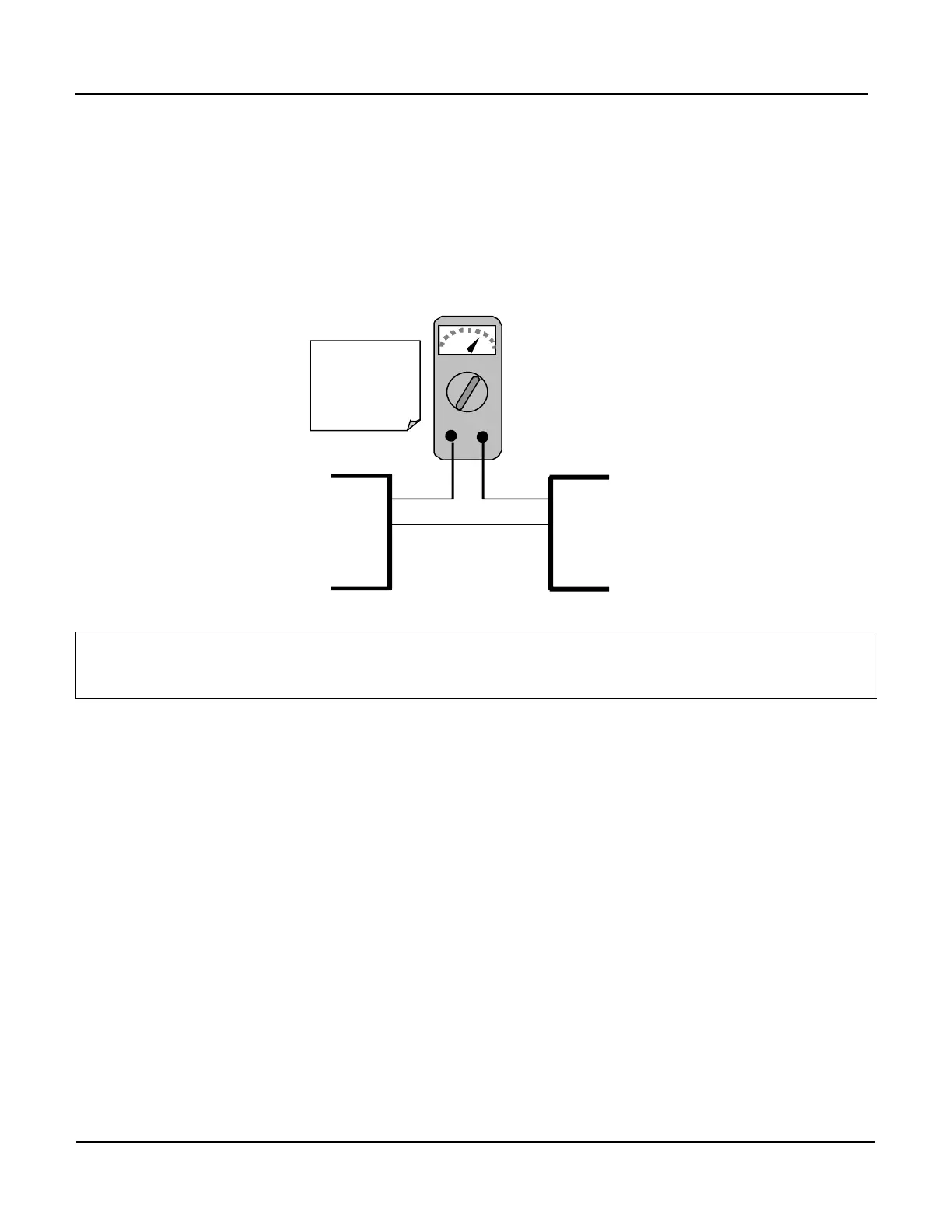
Adjusting the signal zero and span values of the current loop output is done by
raising or lowering the voltage of the respective analog output. This proportionally
raises or lowers the current produced by the current loop option.
Similar to the voltage calibration, the software allows this current adjustment to be
made in 100, 10 or 1 count increments. Since the exact current increment per
voltage count varies from output to output and from instrument to instrument, you
will need to measure the change in the current with a current meter placed in series
with the output circuit (Figure 6-6).
mA
IN OUT
V OUT
I IN +
I IN -
Recording
Device
Analyzer
See Table 3-
the Analog Out
connector on the
rear panel.
Figure 6-6: Setup for Calibrating Current Outputs
NOTE
Do not exceed 60 V between current loop outputs and instrument ground.
 Loading...


