89 Programmable Hardware Manual (PHM)
© Tibbo Technology Inc.
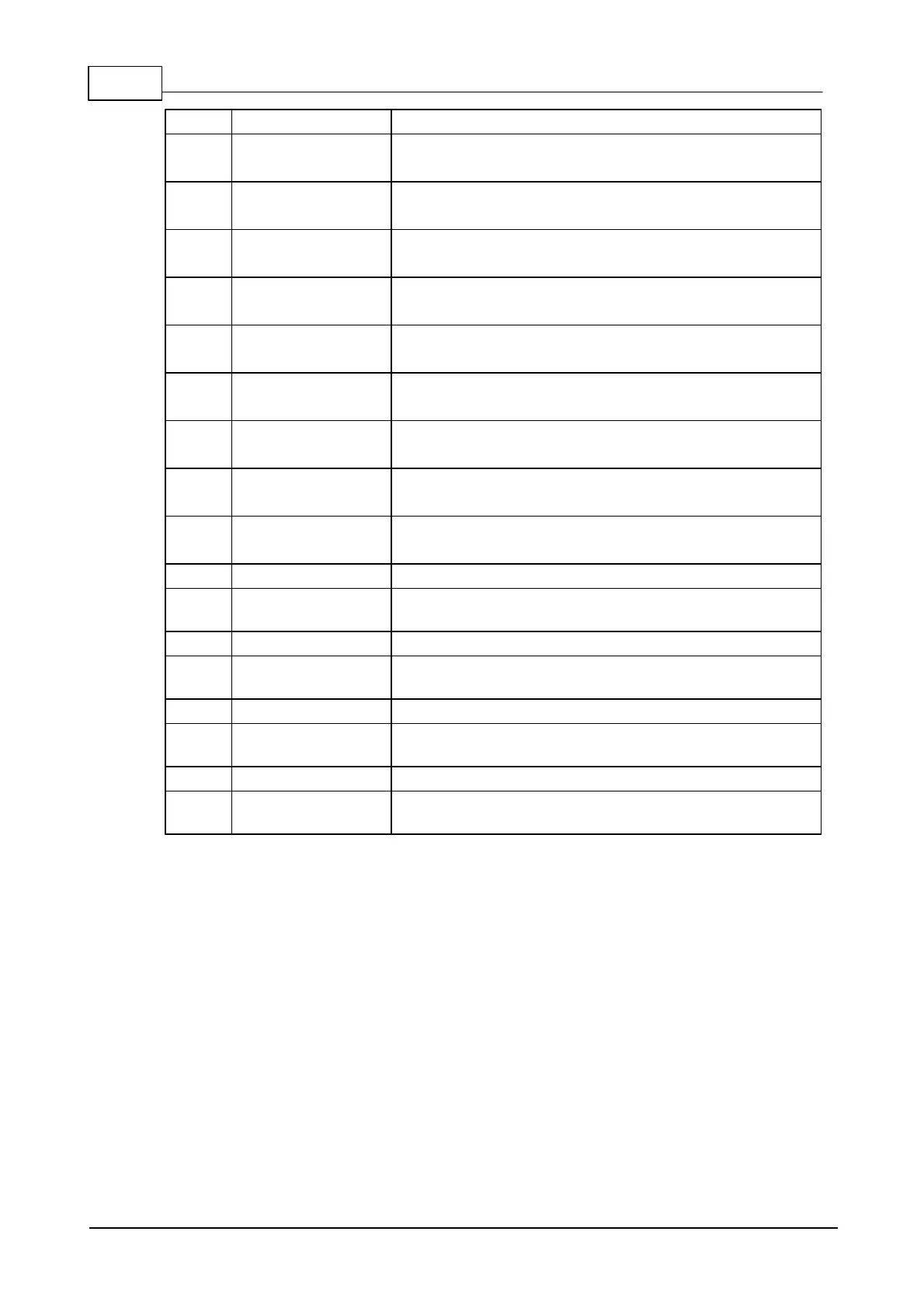
TX, W1, and dout output of the serial port 1.
General-purpose I/O line 19 (P2.3);
interrupt line 3.
General-purpose I/O line 12 (P1.4);
RX, W1, and din input of the serial port 2.
General-purpose I/O line 20 (P2.4);
interrupt line 4.
General-purpose I/O line 13 (P1.5);
TX, W1, and dout output of the serial port 2.
General-purpose I/O line 21 (P2.5);
interrupt line 5.
General-purpose I/O line 14 (P1.6);
RX, W1, and din input of the serial port 3.
General-purpose I/O line 22 (P2.6);
interrupt line 6.
General-purpose I/O line 15 (P1.7);
TX, W1, and dout output of the serial port 3.
General-purpose I/O line 23 (P2.7);
interrupt line 7.
"Clean" 2.5V power output for magnetics circuitry.
Ethernet port, negative line of the differential
output signal pair.
Green Ethernet status LED control line.
Ethernet port, positive line of the differential output
signal pair.
Yellow Ethernet status LED control line.
Ethernet port, negative line of the differential input
signal pair.
Ethernet port, positive line of the differential input
signal pair.
Notes:
1. This line is 5V-tolerant and can be interfaced to 5V CMOS devices directly.
2. This line can serve as an RTS/Wout/cout line of a serial port (provided that this
does not interfere with any other function).
3. This line can serve as a CTS/W0&1in/cin line of a serial port (provided that this
does not interfere with any other function).
4.6.1.1
General-purpose I/O Lines
The EM1202 has 32 general-purpose I/O lines (GPIO0 - GPIO31). 24 of these lines
are combined into three 8-bit ports. All lines are 3.3V, CMOS, 5V-tolerant. Maximum
load current for each I/O line is 10mA.
Simplified structure of one I/O line of the EM1202 is shown on the circuit diagram
below. Each line has an independent output buffer control. When the EM1202
powers up all I/O lines have their output buffers tri-stated (in other words, all I/O
 Loading...
