180Boards
© Tibbo Technology Inc.
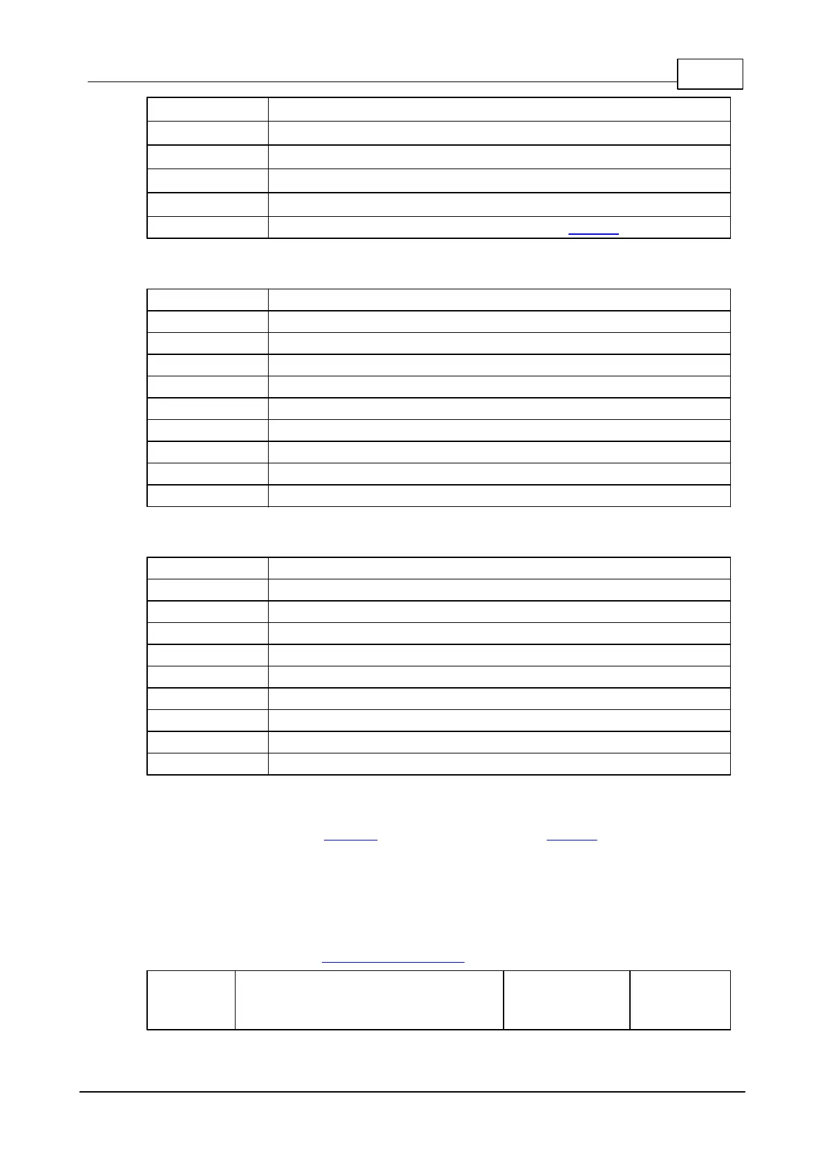
Sensor 7, negative line (-)
Sensor 6, positive line (+)
Sensor 6, negative line (-)
Sensor 5, positive line (+)
Sensor 5, negative line (-)
Vin (connected to the power input of the NB10x0)
Terminal block 3
Relay 3, normally closed line
Relay 3, normally opened line
Relay 2, normally closed line
Relay 2, normally opened line
Relay 1, normally closed line
Relay 1, normally opened line
Terminal block 4
Relay 6, normally closed line
Relay 6, normally opened line
Relay 5, normally closed line
Relay 5, normally opened line
Relay 4, normally closed line
Relay 4, normally opened line
Control Lines
The following lines of the EM1000 module (located on the NB10x0 network board)
are used to communicate with the IB1005 + SB1005.
In the tables below, "output" means an output of the EM1000, and "input" means an
input of the EM1000.
Opto-isolated inputs
For more information see Opto-isolated Inputs.
 Loading...
