166Boards
© Tibbo Technology Inc.
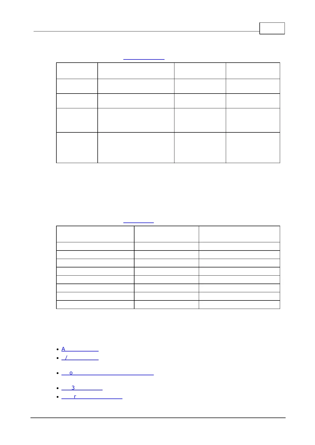
RS232/485 port control
For more information see RS232/485 Port.
Receive line of the serial
port
Transmit line of the serial
port
Mode selection:
HIGH - RS485
LOW (or input*) - RS232
Direction control in RS485
mode:
HIGH - output
LOW - input
*GPIO line configured as input (default state)
LED control
For all LED control lines:
HIGH (or input*) - LED off
LOW - LED on
For more information see LED Control.
*GPIO line configured as input (default state)
Detailed Information
The IB1004 + SB1004 include the following blocks:
·
A/D converter (8 channels, 24 bits, based on the 24-bit AD7712 converter).
·
D/A converter (4 channels, 14 bits, with separate voltage and current outputs,
based on the 14-bit AD7836 converter).
·
Two low-current mechanical relays (both normally-opened and normally-closed
terminals are provided).
·
RS232/485 port (RX/TX signals for the RS232, TX/RX+ and TX/RX- for the RS485).
·
Control lines for 8 LEDs on the LB1001 board.

 Loading...