303 Programmable Hardware Manual (PHM)
© Tibbo Technology Inc.
7.2.9.18
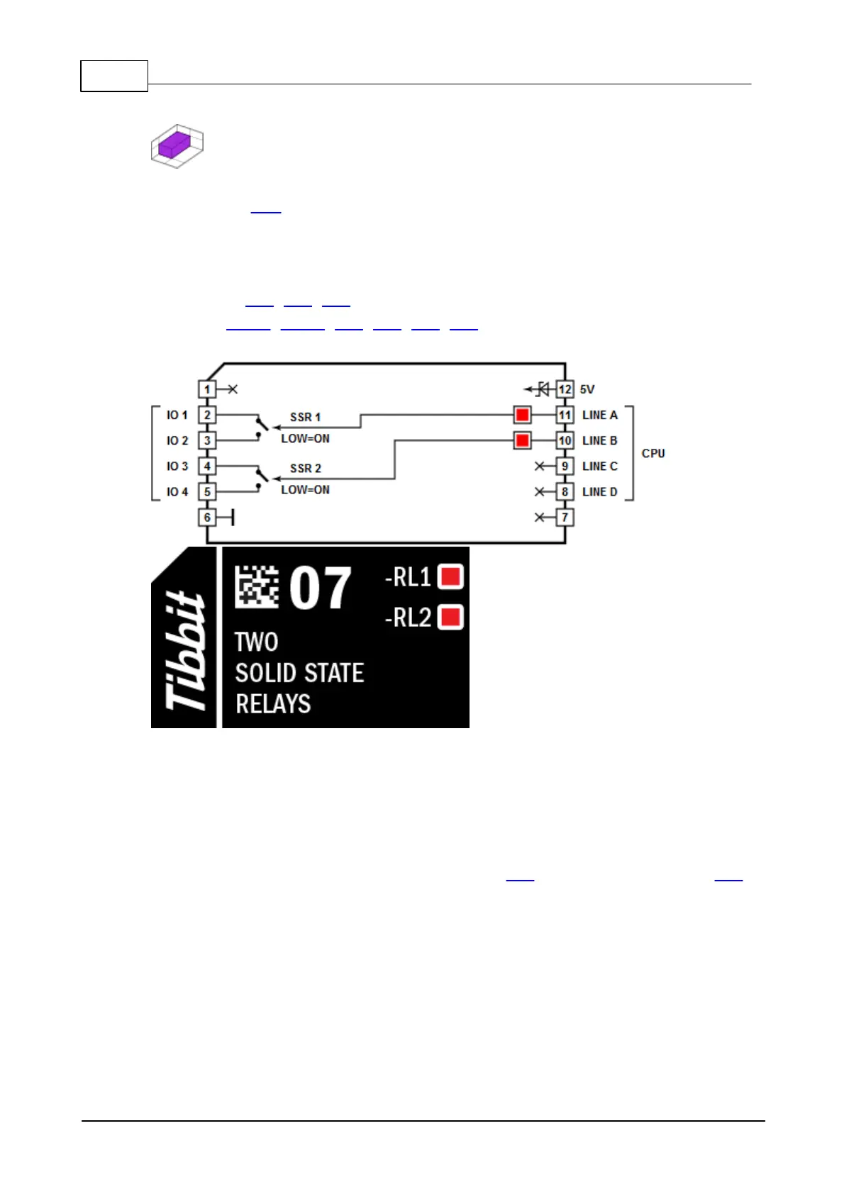
#07, M1S: Two Solid State Relays
Function: Two solid state normally opened relays
Form factor: M1S
Category: Output module
Special needs: ---
Power requirements: 5V/25mA (with both relays activated)
Mates with: #19, #20, #21
See also: #03-1, #03-2, #06, #15, #58, #59
Details
These relays are rated for the maximum load of 1A per relay.
To activate a relay, set the corresponding control line LOW. When left
unconnected, control lines default to HIGH (and, hence, relays are off).
Combine this Tibbit with terminal block devices -- #20 (nine terminal blocks) or #21
(four terminal blocks).
LEDs
There are two red LEDs which are connected to two SSR control lines. LEDs light up
for the LOW state of control lines (i.e. when relays are activated).
 Loading...
