220Boards
© Tibbo Technology Inc.
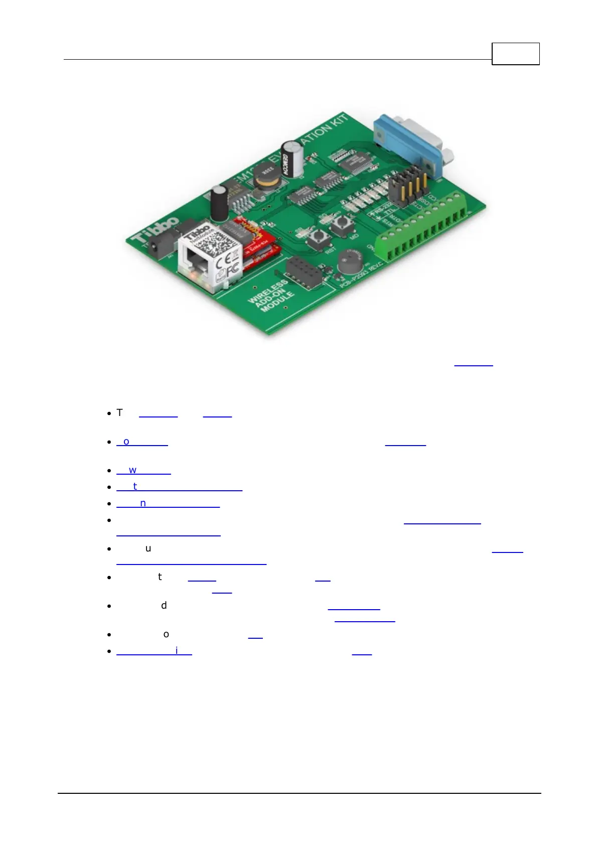
EM1206EV
The EM1206EV Evaluation Board offers a convenient way to test the EM1206
BASIC/C-programmable Ethernet module.
The board features the following components:
·
The EM1206 and RJ203 modules (assembled together and soldered into the
EM1206EV board).
·
Connector for a wireless add-on module, such as the WA2000 Wi-Fi device
(purchased separately).
·
Power jack and a switching power regulator.
·
Multi-channel RS232 port with three RS232 outputs and four RS232 inputs.
·
Expansion connector with GND, 3.3V (Vcc), 12V (Vin), and 8 TTL I/O lines.
·
Eight yellow LEDs to indicate the status of I/O lines (see RS232 port and
Expansion Connector topic).
·
Four jumpers to select between RS232 port and expansion connector (see RS232
port and Expansion Connector topic).
·
Two buttons: setup (connected to the MD line of the EM1206), and reset
(connected to the RST line).
·
Green and red status LEDs (connected to SG and SR lines of the EM1206). Further
information on status LEDs can be found in Status LEDs.
·
Buzzer (connected to the CO line of the EM1206).
·
Supercapacitor (backup power source) for the RTC of the EM1206.
Board structure is further illustrated by this block diagram:
 Loading...
