150Boards
© Tibbo Technology Inc.
The NB1010 carries an onboard regulator that provides stabilized 3.3V power to the
NB1010 itself and to an IB100x interface board, connected to the NB1010 via the
IC1000 interboard cable.
Note, that the IC1000 interboard cable also has lines that carry "raw" input power
(Vin lines). The IB100x board you are using may have its own power supply.
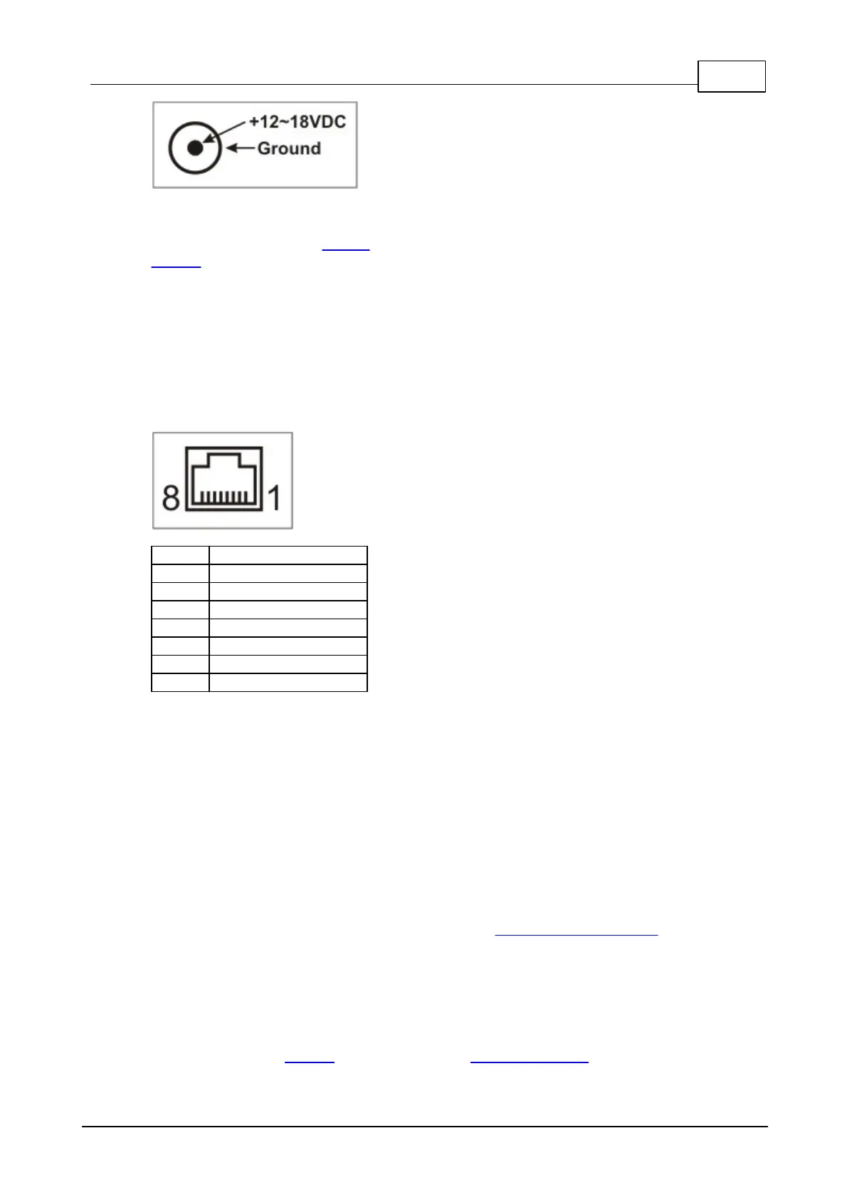
Ethernet Jack
RJ45 Ethernet jack has the standard pin assignment:
Jumpers, Buttons and LEDs
PLL jumper
Leave this jumper open if you want the NB1010 to run at full speed (88.4736MHz).
Close the jumper if you want the NB1010 to run at 1/8th the full speed
(11.0592MHz). Notice, that the jumper state is only recognized after the power-up
or external reset (caused by pressing the reset button). The PLL mode can also be
changed programmatically.
MD jumper and mode button
The function of the mode button is described in Setup Button (MD line). On the
NB1010 board, MD jumper is connected in parallel with the button.
US jumper
This jumper selects the serial port of the NB1010 that will be used for serial firmware
upgrades. When the jumper is opened, serial port 1 is used (TX0 (#17) and RX0
(#19) lines on the IC1000 interboard cable). Interface boards typically implement
serial port 1, thus making serial firmware upgrades possible.

 Loading...