244Development Systems
© Tibbo Technology Inc.
Required initialization code in Tibbo BASIC/C application
This section assumes that you are familiar with Tibbo BASIC/C and TIDE software.
These are documented in the TIDE, TiOS, Tibbo BASIC, and Tibbo C Manual.
Correct preset of serial ports falls outside the scope of this manual. This section will
only remind you that you need to set a correct serial port mode matching the mode
selected by the switches of the TEV-IB0. For RS232 or RS422 mode, set
ser.interface=PL_SER_SI_FULLDUPLEX. For the RS485 mode set
ser.interface=PL_SER_SI_HALFDUPLEX.
Do not forget that all lines of the EM1000 are configured as inputs by default. Any
line that should work as an output should be configured as such. This is done
through the "I/O" (io.) object. The only exception is the TX line that becomes an
output automatically once the serial port is enabled.
6.3.4.2
TEV-IB1
The TEV-IB1 board contains three relays and three optically isolated inputs.
Common, normally closed, and normally opened lines of each relay are available on
the terminal block. Six status LEDs located on the board indicate the state of relays
and opto-inputs.
The relays can switch loads of up to 24V/1A. This rating is for non-inductive loads
only! For inductive loads, the maximum allowed current falls to about 200mA. Status
LEDs 4-6 indicate the state of relays. An LED will be ON when a corresponding relay
is activated.
Each optically isolated input has a pair of (+) and (-) contacts with a 330 Ohm
series resistor and a LED of the photo-couple between them. The input is activated
at a differential voltage of around 4V, and can accept input voltages as high as
24V. Both (+) and (-) inputs are isolated from the rest of the system. Status LEDs
1-3 indicate the state of inputs. An LED will be ON when the current is flowing
through a corresponding input and the input is "triggered".
You can use inputs 1-3 to connect to external sensors. Alternatively, inputs 1 and 2
can be used to attach a Wiegand or clock/data card reader. See below for details.
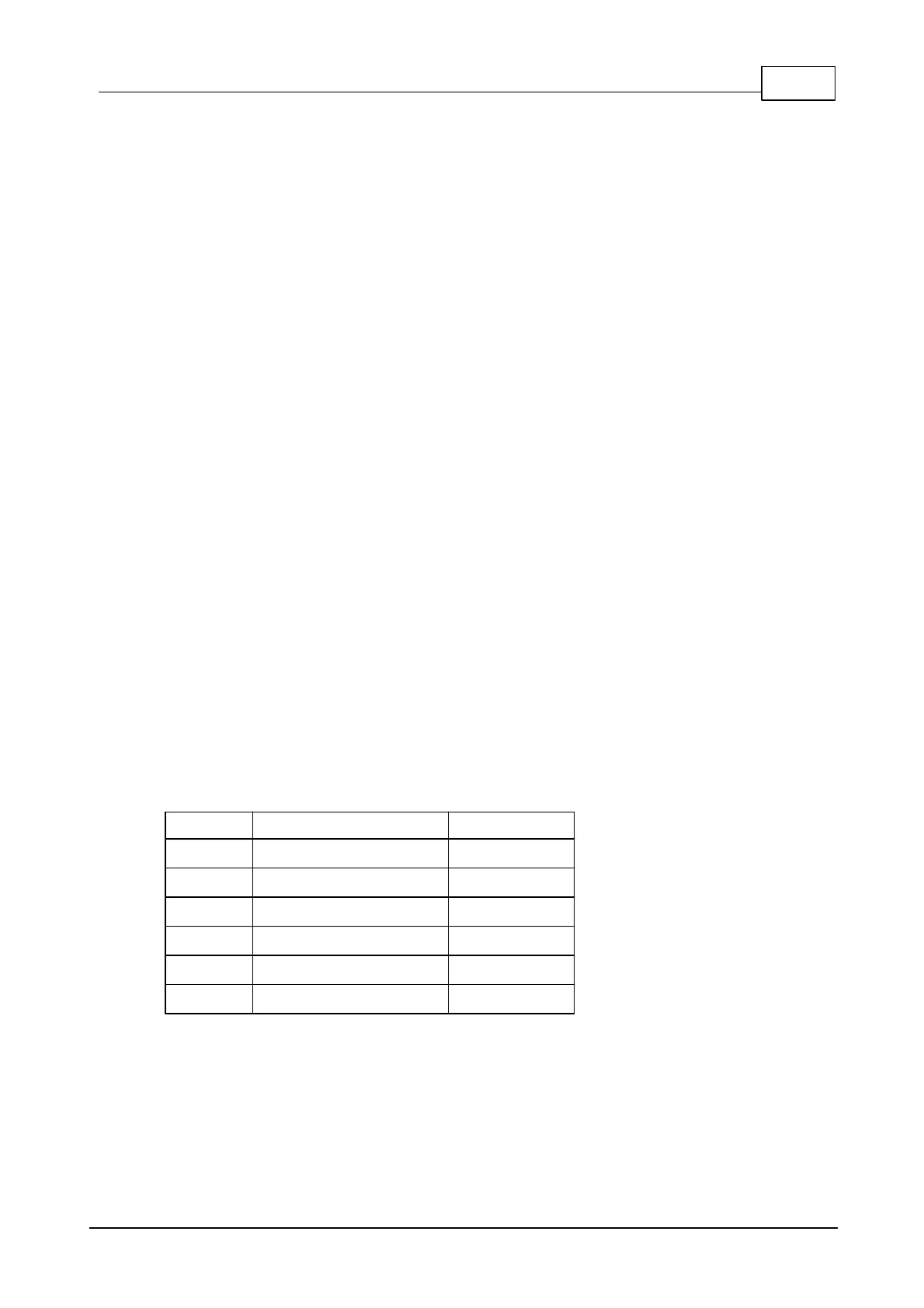
Related EM1000 I/O lines
(1)
Pin number on the TEV-IB1 connector.
(2)
There are four ports, so lines are independent for each port. For example, "TX"
means "TX0" for port 1, "TX1" for port 2, etc.
(3)
Set GPIO line of the EM1000 LOW to activate the relay (do not forget to
configure this line as an output).
 Loading...
