191 Programmable Hardware Manual (PHM)
© Tibbo Technology Inc.
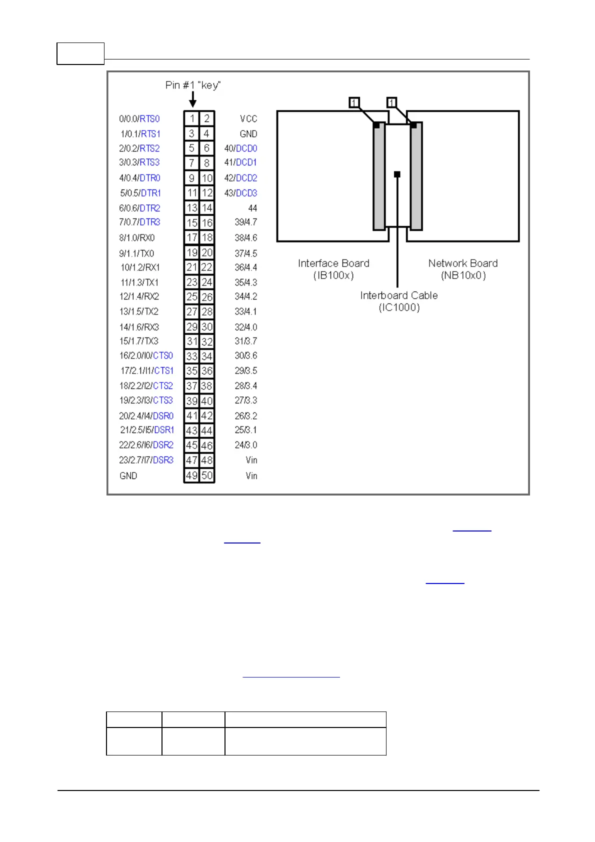
Note 1: indicated pin functions correspond to the pin functions of the EM1000
module (installed on the NB10x0 board). To save space, "GPIO" and "P" were
omitted. For example, "17/2.1" actually means "GPIO17/P2.1". "I1" means "INT1".
Note2: not all pin functions are shown. For example, pin #2 also has "W0out/cout0"
functionality which is not shown on the diagram above. Refer to EM1000
documentation for complete pin function description.
5.3.4.2
LC1000 LED Board Cable
The LB100x LED boards connect to the network board ("NB") or interface board
("IB") via the LC1000 cable. There is a connector on the LB100x, as well as "NB" and
"IB" boards. Connector pin assignment is shown below. LED numbers correspond to
the numbers shown on the mechanical drawing of the LB100x. Pin #1 position of the
connector is also shown on the drawing.
3.3V power from the
"NB" ("IB").
 Loading...
