169 Programmable Hardware Manual (PHM)
© Tibbo Technology Inc.
·
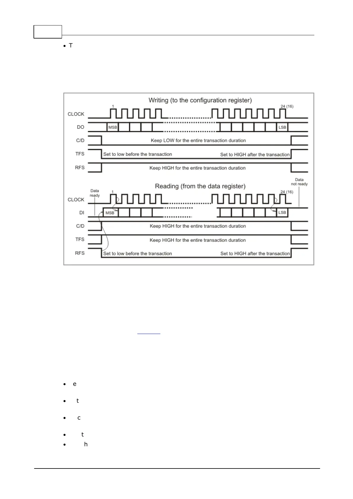
The C/D line defines whether the data is exchanged with the configuration register
(C/D is LOW), or data register that contains the conversion result (C/D is HIGH).
The C/D line must remain stable (HIGH or LOW) for the entire duration of the
transaction.
Read and write "transactions" are illustrated on the diagram below.
The A/D converter has 8 inputs and three control lines -- CHS2, CHS1, and CHS0 --
are used to select the channel. Only one channel can be selected at any given
time.
Preparing to communicate with the A/D converter
Before you start exchanging data with the A/D converter you need to configure
certain GPIO lines of the EM1000 as outputs. These lines are CLOCK, DO, C/D, TFS,
RFS, CHS0, CHS1, and CHS2. In other words, all lines except DI must be configured
as outputs.
Writing to the configuration register
Follow these steps to write to the configuration register:
·
Set the C/D line LOW to indicate that the configuration register access will take
place.
·
Set the TFS line LOW to indicate that this will be a write operation (RFS must
remain HIGH).
·
Place the value of the most significant bit of the configuration word on the DO
line.
·
Set the CLOCK line HIGH.
·
Set the CLOCK line LOW. This will conclude the first clock pulse.

 Loading...